Table of Contents
Advertisement
Quick Links
Advertisement
Table of Contents

Related Manuals for Harman Martin RUSH MH 8 Mini Profile


Summary of Contents for Harman Martin RUSH MH 8 Mini Profile
- Page 1 RUSH MH 8 Mini Profile User Manual...
- Page 2 © 2016 Martin Professional ApS. Information subject to change without notice. Martin Professional and all affiliated companies disclaim liability for any injury, damage, direct or indirect loss, consequential or economic loss or any other loss occasioned by the use of, inability to use or reliance on the information contained in this manual.
-
Page 3: Table Of Contents
Table of contents Safety information ....................4 Introduction ......................8 Before using the product for the first time ............8 Physical installation ................... 9 Fastening the fixture to a flat surface ............. 9 Mounting the fixture on a truss ............... 9 AC power ...................... -
Page 4: Safety Information
Safety information WARNING! Read the safety precautions in this manual before installing, operating or servicing this product. The following symbols are used to identify important safety information on the product and in this manual: Warning! Warning! Warning! Warning! Warning! Warning! Safety Powerful See user... - Page 5 http://www.martin.com If you have any questions about how to install, operate or service the fixture safely, please contact your Martin™ distributor (see www.martin.com/distributors for details) or call the Martin™ 24-hour service hotline on +45 8740 0000, or in the USA on 1-888-tech-180. Respect all locally applicable laws, codes and regulations when installing, operating or servicing the fixture.
- Page 6 Protection from burns and fire Do not operate the fixture if the ambient temperature (T exceeds 40° C (104° F). The surface of the product casing can reach up to 45° C (113° F) during operation. Avoid contact by persons and materials.
- Page 7 Protection from injury Fasten the fixture securely to a fixed surface or structure when in use. The fixture is not portable when installed. Ensure that any supporting structure and/or hardware used can hold at least 10 times the weight of all the devices they support. If suspending from a rigging structure, fasten the fixture to a rigging clamp.
-
Page 8: Introduction
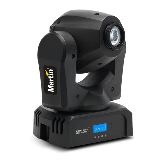
Introduction The RUSH™ MH 8 Mini Profile is a fast, compact moving head profile fixture with an 18 W long-life LED engine. It provides an 8-position plus open gobo wheel, an 8-position plus open color wheel, smooth electronic dimming, strobe effects, and a manually adjustable focus lens. -
Page 9: Physical Installation
Physical installation Warning! Read ‘Safety information’ on page 4 before installing the fixture. The fixture is designed for indoor use only and must be used in a dry location with adequate ventilation. Ensure that none of the fixture’s ventilation slots are blocked and all minimum distances are observed. - Page 10 3. Bolt a rigging clamp securely to the supplied clamp-attachment bracket. The bolt used must be M12, grade 8.8 steel minimum, and fastened with a self-locking nut. 4. Fasten the bracket to the fixture by screwing the two hex socket (Allen) bolts provided fully into holes A in the base of the fixture (see illustrations on right and below) using the washers provided or suitable lock washers.
-
Page 11: Ac Power
AC power Warning! Read ‘Safety information’ on page 4 before connecting the fixture to AC mains power. For protection from electric shock, the fixture must be grounded (earthed). The power distribution circuit must be equipped with a fuse or circuit breaker and ground-fault (earth-fault) protection. Socket outlets or external power switches used to supply the fixture with power must be located near the fixture and easily accessible so that the fixtures can easily be disconnected from... -
Page 12: Fixture Overview
Fixture overview 1 – Display 2 – LEDs Four LEDs provide status information. • DMX: Valid DMX signal present. CLIENT: Fixture operating as a stand-alone client. • • MASTER: Fixture operating as the stand-alone master. • SOUND: Audio signal triggering stand-alone sequence. 3 –... -
Page 13: Control Data Link
Control data link A DMX 512 data link is required in order to control the fixture via DMX. The fixture has 3-pin and 5-pin XLR connectors for DMX data input and output. Up to 32 devices can be linked together on a single daisy chain. The total number of fixtures in one 512-channel DMX universe is limited by the number of DMX channels required by the fixtures. -
Page 14: Fixture Setup
Fixture setup This section explains the fixture characteristics that can be set that determine how it can be controlled and will behave. These settings are made using the menus available from the control panel, and are retained, even when the fixture is powered off. -
Page 15: Stand-Alone Settings
To adjust the setting: 1. Select DMX STATE and press ENTER. The currently set option will blink in the display. 2. Use the DOWN and UP buttons to select SHOW MODE (fixture enters Show Mode), BLACKOUT (fixture blacks out) or HOLD (fixture shows the last effect it was displaying before the DMX signal stopped). -
Page 16: Pan/Tilt Inversion
4. Set all the fixtures in the chain to DMX STATE SHOW MODE. 5. Make sure that the fixtures are not receiving a DMX signal. Sound activation in show mode Show Mode can be combined with sound activation. The fixture has a built-in microphone that can be used to trigger scene changes in sync with a music beat (music trig) when the fixture is running in Show Mode. -
Page 17: Dimmer Settings
Dimmer settings Dimming curve Four dimming curves are available to modify dimmer response. The default is MODE 2. The settings affect response as follows: MODE 1 LINEAR: the increase in light intensity appears to be linear as DMX value is increased. MODE 2 SQUARE LAW: light intensity control is finer at low levels and coarser at high levels. -
Page 18: Backlight
Dimmer calibrate The dimmer calibration function allows you to decrease output to achieve uniform dimming with other fixtures. (If a fixture’s output appears to be low, verify that the DIMMER CALIBRATE level is 100.) To calibrate dimming on a fixture on which the light output is too high: 1. -
Page 19: Home Position Adjustment (Offsets Menu)
Home position adjustment (offsets menu) If the fixture head, gobo wheel, or color wheel does not return to its home position, even after a reset, you can adjust the home position by defining offsets. To make the adjustment from the control panel: 1. -
Page 20: Effects
Effects See ‘DMX protocol’ on page 24 for a full list of the DMX channels and values required to control the different effects. Pan and tilt The fixture’s head can be panned through 540° and tilted through 230° with 16-bit coarse and fine control. Using the control menus it is possible to invert pan or tilt movement. -
Page 21: Colors
Colors The color wheel provides eight colors plus an open white position. See the DMX protocol for details. Colors can be individually selected or scrolled to give split colors. The wheel can be rotated at varying speeds, both clockwise and counter-clockwise, or set to display random colors at slow, medium and fast speeds. -
Page 22: Maintenance
Maintenance Warning! Read ‘Safety information’ on page 4 before servicing the fixture. There are no user serviceable parts inside the fixture. Do not open the housing. Refer any service operation not described in this user manual to a qualified service technician. Disconnect the fixture from mains power before cleaning or servicing. -
Page 23: Replacing The Primary Fuse
Use gentle pressure only when cleaning, and work in a clean, well-lit area. Do not use any product that contains solvents or abrasives, as these can cause surface damage. To clean the fixture: 1. Disconnect the fixture from power and allow it to cool for at least 10 minutes. -
Page 24: Dmx Protocol
DMX protocol Channel Value Function 0-255 Dimmer Coarse: 0-100% 0-255 Dimmer Fine Strobe 8-15 Open 16-131 Strobe, slow to fast 132-167 Fast close, slow open 168-203 Fast open, slow close 204-239 Pulse open and close 240-247 Random strobe 248-255 Open Color Wheel Open 1-14... - Page 25 Channel Value Function Random Colors 244-247 Fast cont. 248-281 Medium 252-255 Slow Gobo Wheel Open 1-14 Open → Gobo 1 Gobo 1 16-29 Gobo 1 → Gobo 2 Gobo 2 31-44 Gobo 2 → Gobo 3 Gobo 3 46-59 Gobo 3 → Gobo 4 Gobo 4 61-74 Gobo 4 →...
- Page 26 Fixture Control Settings No function (disables calibration) 10-14 Reset fixture 15-19 No function 20-24 Reset color 25-29 No function 30-34 Reset pan and tilt 35-54 No function 55-59 Enable calibration 60-64 Linear dimmer curve 65-69 Square law dimmer curve (default) 70-74 Inverse square law dimmer curve 75-79...
-
Page 27: Control Menus
Control menus To access the control menus, press the MENU button. Use the UP and DOWN buttons to navigate the menus. Select a menu option with the ENTER button. For more information, see ‘Using the control menus’ on page 14. Default fixture settings are shown in bold. - Page 28 Menu Sub-menu Explanation Tilt Color Manual Test Manual control of all effects Gobo Shutter Dimmer LED Temp. Temperature readout Optimize cooling for light Auto output intensity Optimize cooling for Fan Mode quietness (output intensity is reduced if necessary to limit temperature) Currently installed firmware Firmware Version version...
-
Page 29: Troubleshooting
Troubleshooting This section describes a few common problems that may occur during operation and provides some suggestions for easy troubleshooting: Symptom Potential Causes Remedies No light from fixture, Power supply issue Ensure that the mains or fans not working. such as blown fuse, supply is connected and faulty connector or supplying power to the... -
Page 30: Specifications
Specifications Physical Dimensions (LxWxH) ....... 157 x 237 x 327 mm (6.1 x 9.3 x 12.9 in.) Weight ..................4.5 kg (9.9 lbs.) Dynamic Effects Color wheel ......8 colors plus open, variable and random rotation Gobo wheel ....8 static gobos plus open, variable and random rotation Strobe ..... - Page 31 Construction Color ......................Black Housing .......... High impact flame retardant thermoplastic IP rating ....................IP 20 Installation Mounting points ............Bracket for rigging clamp Location ....Dry location only, must be fastened to surface or structure Orientation ..........Vertical (head down if suspended) Minimum distance to illuminated surfaces ........
- Page 32 Canadian EMC ..............ICES-003 Class A Australia/NZ (pending) ................RCM Included Items Power cable, 1.9 m without mains plug Power cable, 1.9 m with US plug Bracket for rigging clamp attachment Accessories Installation hardware Half-coupler clamp ..............P/N 91602005 G-clamp ..................P/N 91602003 Quick-trigger clamp ..............
- Page 33 Photobiological Safety Warning The label shown below is displayed on this product. If it becomes difficult or impossible to read, it must be replaced using the illustration below to reproduce a new label sized 45 x 18 mm, in black on a yellow background. RISK GROUP 2 CAUTION.
Need help?
Do you have a question about the Martin RUSH MH 8 Mini Profile and is the answer not in the manual?
Questions and answers