Table of Contents
Advertisement
Advertisement
Table of Contents

Related Manuals for Matsutec HA-102


Summary of Contents for Matsutec HA-102
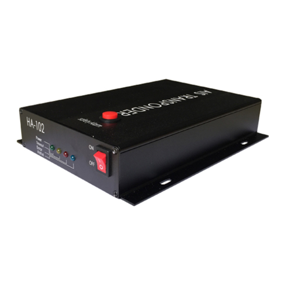
- Page 1 CLASS B AIS TRANSPONDER HA-102...
-
Page 2: Table Of Contents
CLASS B AIS TRANSPONDER HA-102 INSTRUCTION MANUAL TABLE OF CONTENTS GENERALS ............1 2. PRODUCT INTRODUCTION ..........1 2.1 APPLICATION ........................... 1 2.2 O ......................... 1 PERATION RINCIPLE 3. FUNCTIONS AND FEATURES ..........2 3.1 M : ..........................2 UNCTIONS 3.2 T... -
Page 3: Generals
1. Generals This manual covers all information about interface, electrical and mechanical data related to research and design, so as to make users have more overall understanding about product’s performance and make good use and maintenance of the product. Software versions may be upgraded in future without notice to users. Please follow upgraded information closely through our website. -
Page 4: Functions And Features
AIS Class-B system block diagram see Figure 1. Figure 1 AIS Class-B AIS system Block Diagram 3. Functions and Features 3.1 Main Functions: 1. Power supply: Power supply: Rated Voltage: +12VDC Extreme Voltage: +9.6VDC,+15.6VDC 2. Electrical functions are in accordance with IEC 62297-1 3.... -
Page 5: Technical Features
5. Transponder has external serial data interface (RS-232). 6. Transmit and receive safety message 7. Support two operation mode, Carrier-sense mode, assigned mode. 8. Internal GPS receiver, as data source for positioning, COG and SOG. 9. Led indication for power, transmit, receive channel. 10. -
Page 6: Installation
2) This device uses 12V supply voltage. Before put through device power supply, confirm DC supply voltage in normal state, don’t hot-plug device, otherwise internal circuits and chips might be burned out. 3) This device is a power radio transmitter, 20cm above from users and other personnel to the installation location of transmitting antenna to avoid device’s radiation. - Page 7 Figure 2 Connection Diagram Installation steps are as follows: During the installation of GPS antenna, after fixing the GPS antenna, connect TNC plug of GPS feed cable to transponder’s TNC socket. Pay attention to the following points during the installation of GPS antenna: ①...
- Page 8 1. During the installation of VHF antenna, after fixing the VHF antenna, connect N plug of VHF feed cable to transponder’s N socket. Pay attention to the following points during the installation of VHF antenna: ① Each VHF antenna can only connect one AIS device, can not be shared VHF antenna with other devices.
- Page 9 Figure 3 VHF antenna installation diagram Installation steps are as follows: ① Using self-tapping screws to fix the transponder on bridge table or waterproof wall of wooden boat. ② Make good connection with transponder according to first GPS antenna, VHF feed cable afterwards, finally power/data cable plugs.
-
Page 10: Structural Characteristics、 Configuration、 Interface Descriptions And Electrical Performance Specification
Structural characteristics、Configuration、 Interface descriptions electrical performance specification Structural characteristics Volume and Quality ① Dimension:205.5 mm× 170mm× 49.5mm(L× W× H) ; ② Weight:1.1kg。 5.2 Configuration Table 5-1:AIS transponder configuration Item Quan Transponder 1 set Power/Data Cable 1 pc User’s manual 1 pc Accessory Part 1 pc *GPS antenna, VHF antenna and cables are optional. - Page 11 5.3.2 Detailed description of interfaces DC interface (Figure 4) Red cable to Black cable positive to negative pole Figure 4 DC interface diagram GPS antenna interface TNC RF interface N-J Data/Power interface...
-
Page 12: Electrical Performance Specifications
5.4 Electrical performance specifications Modulation mode: GMSK, FSK Data speed: 9600b/s±50ppm(GMSK), 1200b/s±30ppm(FSK) Channel interval: 25kHz Working frequency: 156.025MHz~162.025MHz(AIS) Antenna Impedance: 50Ω Rated working voltage: +12VDC Extreme Working Voltage: +9.6 VDC ~+15.6VDC Table 5-3:Class-B main specifications Item name Specification Transmitting power... -
Page 13: Working Condition And Using Method
6 Working condition and using method 6.1 Working Condition According to the requirements of 4.2, connect device and turn on the power supply, red, yellow, blue, green LED on device flash twice, then yellow and green LED will keep constant light, and other LED go out. At this time, the device state at the initialization and GPS positioning. -
Page 14: Equipment Maintenance And Common Troubleshooting
7 Equipment maintenance and common troubleshooting 7.1Equipment maintenance At all time keep the device clean to make the equipment 1、 work in ventilated, dry, stable temperature conditions. 2、 Don’t move or vibrate the device when electricity is 3、 Do not place acid, alkaline materials on equipment surface. -
Page 15: Transport And Storage
8. Transport and Storage 8.1 Transport Requirement Operate strictly in accordance with transport marks on package box. Packaging parts should be stacked neatly, reliably and placed in a balance and not be biased towards one side. c) Not allow to ship the device with flammable, explosive, corrosive items in the same car.
Need help?
Do you have a question about the HA-102 and is the answer not in the manual?
Questions and answers