
Subscribe to Our Youtube Channel
Related Manuals for rada Acu-T3 1.1664.001


Summary of Contents for rada Acu-T3 1.1664.001
- Page 1 Rada Acu-T3 Digital Mixing Valve PRODUCT MANUAL IMPORTANT Installer: This Manual is the property of the customer and must be retained with the product for maintenance and operational purposes. 1108900-W2-L...
-
Page 2: Table Of Contents
Patents and Design Registration ............5 Safety : Warnings ..................5 Specifications ..................6 Installation ....................7 General ....................7 Make the connections to the Rada Acu ..........8 Commissioning ..................9 Operation ....................10 User Modes ..................10 Programming ..................13 General .................... - Page 3 Customer Care ..................36 ATTENTION. The Rada Acu must be commissioned in order to activate and set-up the automatic duty flushing function. Please refer to the following instructions to achieve this. Default Password: 1 1 1 1 User Defined Password: _ _ _ _...
-
Page 4: Description
Type 3 valve under the BUILDCERT TMV3 scheme. Application The approved designations for Type 3 Valves are as follows: Model Designation Code Rada Acu HP-WE For Type 3 Valves refer to the TMV3 Requirements Manual Key Features •... -
Page 5: Patents And Design Registration
Patent Applications: Europe: 2 227 647 USA: US-2010-0282326-A1 China: CN101918743A India: 1306/MUMNP/2010 Design Registration: 001065023-0004 SAFETY : WARNINGS The function of this Digital Mixing Valve (DMV) is to deliver water consistently at a desired temperature. This requires that: It is installed, commissioned, operated and maintained in accordance with the recommendations given in this Manual. -
Page 6: Specifications
SPECIFICATIONS For Type 3 installations, the supply conditions specified in section: ‘Type 3 Valves, Application’ in the TMV3 Requirements Manual take precedence over the operating parameters which follow. Standards and Approvals This Digital Mixing Valve complies with all relevant directives for CE marking. This Digital Mixing Valve is a type 1 electronic, panel mounted control. -
Page 7: Installation
Warning! Failure to achieve parallel inlet supply pipework will result in the inability to service the mixing valve. Do not install the Rada Acu opposite a mirror, a highly reflective surface or into direct sunlight. Caution! The Digital Mixing Valve (DMV) must be installed in a dry area and where it will not freeze. -
Page 8: Make The Connections To The Rada Acu
Make the connections to the Rada Acu Connect the hot and cold water supplies to the inlet isolators, connections are: Hot: Left, Cold: Right, when viewed from the front. Caution! It is essential that the supply pipework is thoroughly flushed through before connection to the digital mixing valve. -
Page 9: Commissioning
COMMISSIONING ATTENTION. The Rada Acu must be commissioned. Please refer to the following instructions to achieve this. Commissioning must be carried out in accordance with these instructions, and must be conducted by designated, qualified and competent personnel. Notes! For Healthcare Installations, all results must be recorded. -
Page 10: Operation
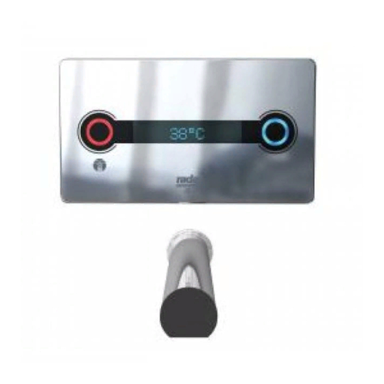
OPERATION Blue Sensor (Cold) Red Sensor (Hot) Spout Sensor (On/Off) Note! The sensors are designed to operate at a distance of up to 60 mm. There is no need for the user to touch the spout or control panel. User Modes The Digital Mixing Valve (DMV) has 4 different modes: Patient, Clinical, Surgical or Free Mode (user defined), to change modes refer to section: ‘Programming’. - Page 11 Clinical Mode: • Standby - no illumination, interface will read: ‘Non touch’ • Activation of the water supply via the spout sensor • Water flow stops 2 seconds after the user removes their hands • No temperature adjustment offered to the user •...
- Page 12 Free Mode • Standby - no illumination, interface will read: ‘Non touch’ • Activation of the water supply via the spout sensor • Water flow stops 2 seconds after the user removes their hands, unless the product has been placed in time flow mode by the selection of flow duration •...
-
Page 13: Programming
PROGRAMMING General Programming via the interface is accessed by swiping/tapping the magnetic key between the red sensor and ‘T-Logic’ symbol, this will take you to the ‘Main Menu’. The menus are navigated by scrolling with the blue sensor and selecting with the red sensor. - Page 14 ‘Usage Count’ Displays the number of times the DMV has been operated since installation (stored within the PCB, replacing or re-programming the PCB will reset this to zero). ‘Last Used’ Displays (in hours) the time elapsed since the last operation. ‘Settings’...
-
Page 15: Main Menu
Main Menu Non touch Disable Acu De-Activated Serial No x x x x x x Useage Count x x x x x x Last Used x x x x x x Settings Settings Refer to: Valve Setup Valve Setup Refer to: Service Service Refer to:... -
Page 16: Settings
Settings The settings menu allows you to scroll through and view the current valve settings. Activate the blue sensor to scroll to the next setting, activate the red sensor at any time to go back to the main menu. Settings Patient Current Mode Blend... -
Page 17: Valve Setup
Valve Setup The valve setup menu allows you to change the valve mode, activate the duty flush or reset the password, refer to menus: ‘Set Mode’, ‘Flush Setup’, or ‘Set Password’. To exit the valve setup menu, scroll through and select exit to return to the main menu. -
Page 18: Set Mode
Set Mode ‘Set Mode’ is accessed via the valve setup menu and allows you to change the valve mode to any of the 3 pre-programmed modes or set the user defined ‘free mode’. Set Mode Patient Blend 41°C 33°C to 41°C Clinical Temp Adj N Yes or No? -
Page 19: Flush Setup
Flush Setup ‘Flush Setup’ is accessed via the valve setup menu and allows you to activate or deactivate the duty flush feature, set the flow duration and temperature for the flush. Flush Setup Activate No Enter Flow Time (Duty Flush Cycle) Scroll through 1 to 59 minutes Flow with the blue sensor, confirm... -
Page 20: Set Password
Set Password ‘Set Password’ is accessed via the valve setup menu and allows you to change the factory default password to your own 4 digit combination. Set Password Set First Digit? Scroll through 0-9 with - 0 0 0 the blue sensor, confirm with the red sensor. -
Page 21: Service
Service The service menu allows you to perform a manual duty flush, valve disinfection, or commissioning, refer to menus: ‘Manual Flush’, ‘Disinfection’, or ‘Commission’. To exit the service menu, scroll through and select exit to return to the main menu. Service Enter Password Scroll through 0-9 with the... -
Page 22: Manual Flush
Manual Flush ‘Manual Flush’ is accessed via the service menu and allows you to perform a manual duty flush. Manual Flush Activate No/Yes? Toggle Yes/No with the Confirm No blue sensor, confirm with the red sensor. Yes or No? Flushing Manual Flush Duration The manual flush duration is the same as that set in Manual Flush... -
Page 23: Disinfection
Disinfection ‘Disinfection’ is accessed via the service menu and allows you to perform a disinfection cycle. Disinfection Disinfect No/Yes? Toggle Yes/No with the Disinfect No blue sensor, confirm with the red sensor. Yes or No? Confirm No/Yes? Toggle Yes/No with the Confirm No blue sensor, confirm with the red sensor. -
Page 24: Commissioning
Commissioning ‘Commissioning’ is accessed via the service menu and allows you to commission the valve, refer to the TMV3 Requirements Manual to assist with the temperature recording as required by the commissioning and in-service test procedures. Commission Start No/Yes? Toggle Yes/No with the Start No blue sensor, confirm with the red sensor. -
Page 25: Maintenance
MAINTENANCE General Maintenance must be conducted by designated, qualified and competent personnel. Warning! Isolate power supply and water supply when any maintenance work is carried out on the Digital Mixing Valve (DMV). The DMV may contain hot water, so care must be taken when draining any residual water. -
Page 26: Cleaning
Cleaning External surfaces can be cleaned with products associated with basin cleaning referenced in the NHS cleaning manual. Caution: Plated or plastic fittings should only be cleaned using a mild detergent or soap solution and wiped dry with a soft cloth. It is understood that additional chemical disinfection is widely used to clean water systems. -
Page 27: Filters And Non Return Valves
Pall medical water filters can easily be installed onto the Rada Acu Spout by using a Pall Filter Connector (refer to section: ‘Spare Parts’). Filters and Non Return Valves Hot water entering the cold supply, or vice versa, indicates that immediate maintenance of the non return valve is necessary. - Page 28 Unscrew the 4 PCB box mounting screws using a 3 mm hexagonal key and remove the PCB box. Note! To aid servicing, secure the PCB box onto the frame with the hook. PCB Box Screws Hook the PCB Box onto the frame Isolate the hot and cold water supplies using a 3 mm hexagonal key or a flat faced screwdriver.
- Page 29 Clean or replace the filters and/or the non return valve assemblies. Make sure that the non return valve assemblies are correctly fitted and pushed fully into the valve assembly and refit the filters. Filters Non Return Valve Assemblies ‘O’ Seal Valve Assembly ‘O’...
-
Page 30: Fault Diagnosis
Hot and cold inlet supplies reversed, rectify. Continuous flow. DMV will not switch off, isolate power supply and water supply and contact Rada Customer Care or your local agent. DMV takes at least Remove and clean or renew the non return 30 seconds to reach valves. - Page 31 Blend temperature too hot. Make sure that the before the completion inlet temperatures are within specification, refer of the programmed to section: ‘Specifications’. timed flow period If the fault has not been rectified contact Rada (safety feature). Customer Care or your local agent. 1108900-W2-L...
-
Page 32: Self Diagnostic Errors
O/C THERMIS secure. Fault with the thermistor, replace. If the fault has not been rectified contact Rada Customer Care or your local agent. Blend temperature too hot at the control thermistor, reset the DMV by switching the power supply to the DMV, OFF then ON. - Page 33 DMV, OFF then ON. Fault with the Valve Assembly, replace. MOTOR STUCK If the fault has not been rectified contact Rada Customer Care or your local agent. The maximum continuous flow time has been exceeded.
-
Page 34: Spare Parts
SPARE PARTS Recommended Spares Minimum Stock List Spares per quantity of Digital Mixing Valves installed Component 6-20 21-50 1664.100 Mixing Valve Assembly 1664.102 Thermistor Assembly 1664.103 Non Return Valve and Filter Assembly 1664.107 Screw Pack 1664.108 PCB Box Assembly 1664.109 Front Facia 1664.110 Flow Straightener 1664.116 Seal Pack 1664.119 Spout Sensor... - Page 35 1664.106 1664.104 Inlet Clamps (includes Inlet Isolator front and rear clamps) 1664.122 Inlet Filters (x2) 463.84 Magnetic Key (x4) 1664.103 Non Return Valve and Filter Assembly (x2) 1664.114 1664.102 Access Panel Thermistor Assembly 1664.105 1664.100 Outlet Connector Mixing Valve Assembly Assembly 1664.124 Solenoid...
- Page 36 CUSTOMER CARE Your product has the benefit of our manufacturer’s guarantee which commences from date of purchase or from the date of commissioning when product commissioning has been conducted by the UK Rada Commercial Field Team (available UK Only). Please visit www.radacontrols.com or contact your local agent for all terms and conditions including details of the Rada commissioning service for the UK UK Customer Service &...
Need help?
Do you have a question about the Acu-T3 1.1664.001 and is the answer not in the manual?
Questions and answers