
Subscribe to Our Youtube Channel
Related Manuals for rada DRV40


Summary of Contents for rada DRV40
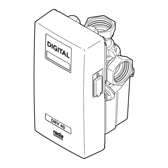
- Page 1 DRV40 Digital Recirculation Valve Important! This Manual is the property of the customer and must be retained with the product for maintenance and operational purposes. Product Manual...
-
Page 2: Table Of Contents
CONTENTS Safety - Warnings ..................4 Advice ....................... 4 Introduction ..................... 5 Description ....................5 Pack Contents ..................6 Dimensions ....................7 Specification .................... 8 Default Settings ..................9 Installation ..................... 10 General ....................10 Recirculation Circuit - Plumbing Schematic ........12 Commissioning .................. - Page 3 System Performance ................38 Pump Capacity ................... 38 System Safety Measures ..............38 Maintenance and Spare Parts .............. 39 Batteries ..................... 39 Disassembly ..................40 Electronics Module ................41 PCB Connections ................44 DRV ....................45 Valve Calibration ................53 Fault Diagnosis ..................
-
Page 4: Safety: Warnings
SAFETY: WARNINGS The function of this DRV (Digital Recirculation Valve) is to deliver water consistently at a safe temperature. This requires that: It is installed, commissioned, operated and maintained in accordance with the recommendations given in this Manual. Periodic attention is given, as necessary, to maintain the product in good functional order. -
Page 5: Introduction
Guidelines/Approved Codes of Practice. INTRODUCTION The Rada DRV40 Digital Recirculation Valve is specified to meet the highest standards of safety, comfort and economy as demanded by todays users. The Rada DRV40 is designed, manufactured and supported in accordance with accredited BS EN ISO 9001:1994 Quality Systems. -
Page 6: Pack Contents
2 x Electronics Module Screws 1 x PC USB Cable (for connecting Laptop/PC to Electronics Module) 1 x USB stick (contains USB cable driver software, DRV Programming Software and DRV40 product guides) *2 x CR - P2 6V Batteries not supplied. -
Page 7: Dimensions
DIMENSIONS All dimensions are nominal. 172 mm 55 mm AF Hex 144 mm 1-1/2 BSP Internal 268 mm power cable length 67 mm 240 mm 50 mm minimum 140 mm recommended clearance... -
Page 8: Specification
Duty cycle Continuously rated Auxiliary Relay (see Alerts - Activate Relay on Alert) Relay Type Single pole changeover relay contacts Power Supply 230V AC / 24V DC Supply Fuse 2 Amp The Rada DRV40 conforms to the CE marking requirements. -
Page 9: Default Settings
DEFAULT SETTINGS The following table shows the factory default settings of the Rada DRV40. These values can be altered using the 'DRV Programming Software' available to install from the USB stick supplied. Temperatures Adjusted Setpoint 49 °C Setpoints 68 °C Default 49 °C... -
Page 10: Installation
'Specification'. Care must be taken during installation to prevent any risk of injury or damage. The DRV40 must be installed in a dry area where it will not be able to freeze (minimum ambient temperature of 2°C Inlet isolating valves (full flow type) must be installed close to the DRV40 for ease of maintenance. - Page 11 These clearance dimensions are recommended for maintenance purposes. 2 x CR - P2 6V Batteries are not supplied with the DRV40, but must be fitted prior to installation. Do not fit rechargeable batteries. (Also see 'Maintenance and Spare Parts'.) CAUTION! RISK OF FIRE OR PRODUCT DAMAGE IF INCORRECT TYPE OF BATTERY IS FITTED.
-
Page 12: Recirculation Circuit - Plumbing Schematic
Recirculation Pump Safety Valve Strainer / Filter Check Valve Shower Stop Valve Thermometer Full Bore Isolating Valve Cold Water Pressure Reducing Valve Hot Water Blend Circuit Needle Valve Mixed Water Flow indicator Water Outlets Heater Cold Water Supply Recirculation Circuit - Plumbing Schematic... - Page 13 Before fitting to the pipework, it is recommended that suitable unions are fitted to the inlets and outlet. This will enable the DRV to be easily removed, if required. Flush pipework thoroughly (minimum of 5 minutes). Fit the DRV to the pipework. Attach the Electronics Module and secure using the circlip supplied.
- Page 14 Module with the 2 x 4mm hexagon socket screws provided. Note! The Electronics Module must be closed for the DRV40 to function. C o m m i s s i o n t h e D RV 4 0 a n d...
-
Page 15: Commissioning
The LCD display will indicate the outlet water temperature and the outlet water temperature setpoint. The setpoint is preprogrammed to 49ºC. This can be altered using the 'DRV Programming Software' on the USB stick supplied. Rada drv40 Temp. 48˚C Setpoint 49˚C... -
Page 16: Operation
Connect the Laptop/PC to the Electronics Module with the PC USB Cable supplied. Connect the cable to any USB port on the laptop/PC and the serial port on the Electronics Module of the DRV40. Run the 'DRV Programming Software' by double clicking the icon on the desktop or search for and run the file 'Titan Terminal CSharp.exe'. -
Page 17: Com Port
COM Port Locate the DRV40 by selecting the correct COM Port. The COM Port can be confirmed using the Device Manager utility within the Windows OS. Note! Make sure the USB Driver has been installed. Example of Windows XP Device Manager... - Page 18 The control screens can be selected individually by clicking on each of the tabs. The general status of the DRV40 is displayed on the right of the screen. Valve Units - displays the temperature units. Valve Status - displays the DRV40’s current operating status.
-
Page 19: Drv Information
Version - The version of Rada DRV40 control software. Manufacturing Date - The date the DRV40 was built. These data fields are read only and can only be changed by updating the DRV40 internal software (only to be performed by a qualified service engineer). -
Page 20: Temperatures
Adjusted Setpoint Input 'Adjusted Setpoint' value Click 'Set' to transfer the value to the DRV40 The 'Adjusted Setpoint' value is displayed on the DRV40 as 'Setpoint'. To change the 'Adjusted Setpoint' back to the default value, click 'Reset to Default'. -
Page 21: Setpoints
Alter the 'Max', 'Min' and 'Default' values as required for the application. Switch 'Valve Control' to 'OFF'. Click 'Set' to transfer the values to the DRV40. Switch 'Valve Control' back 'ON'. The 'Setpoint Default' value is displayed on the DRV40. - Page 22 Switch the 'Valve Control' to 'OFF'. Click 'Set' to transfer the value to the DRV40. Switch 'Valve Control' back 'ON'. Alerts - optional (Also see 'Alerts - Explained' and 'Preset Display Alerts') Input the 'Above Setpoint' and 'Below Setpoint' values.
-
Page 23: Setpoints - Explained
The 'Default' value is the temperature the DRV will return to should the power be lost and the DRV40 is reset. The 'Default' is adjustable, but cannot be more than the 'Max.' (maximum) value or less than the 'Min.' (minimum) value. -
Page 24: Alerts - Explained
Relay (also see 'PCB Connections') DRV40 will also issue an alert if the preset 'Error Temp' value located under the 'Setpoints' tab is exceeded (the default is 65 °C). If the 'Error Temp' is reached, the display on the DRV40 will read 'Error Temp', the aforementioned relay will be activated and the DRV40 will assume a position where no hot water can enter the blend circuit. - Page 25 Example 2 SHUT DOWN TO FULL COLD 60°C ‘Error Temp.’ Max. ALERT 49°C 45°C (2°C ‘Above Setpoint’) Setpoint 43°C ‘Setpoint’ 41°C ( 2°C ‘Below Setpoint’) 38°C Min. ALERT Cold Important! The 'Error Temp' value cannot be set lower than the sum of the 'Max.' + 'Above Setpoint' values.
-
Page 26: Preset Display Alerts
Preset Display Alerts The DRV40 is supplied with two Preset Display Alert levels: Level 1 - Alert preset: 2°C 'Above Setpoint' DRV40 will display 'Temp High' preset: 2°C 'Below Setpoint' DRV40 will display 'Temp Low' Level 2 - Error preset: 6°C above default setpoint DRV40 will display 'Error... -
Page 27: Thermal Disinfection
Thermal Disinfection IMPORTANT! PLEASE READ CAREFULLY The thermal disinfection mode of the DRV40 is not an automated process. It is manually activated by the supervisor to increase the temperature of the blend circuit to equal the temperature of the hot supply. The circuit pipework and outlets can be thermally disinfected regularly as part of good bacterial infection control. - Page 28 'Cool Down' button within the 'Disinfection' screen. This will switch the DRV40 to its full cold position and allow the blend circuit to be reduced gradually to a safe temperature level*. Make sure the blend circuit temperature returns to normal operation within the 'Disinfection Timeout' period (see 'Disinfection Cycle').
- Page 29 'Disinfection Timeout' is set to 30 minutes then the DRV40 has that amount of time to complete the disinfection and cool down before entering an error condition and switching to full cold.
- Page 30 Disinfection Cycle Warning! Due to the scalding temperature, the disinfection process must be supervised. The DRV40 should be monitored whilst in disinfection mode and no one should be allowed to approach within 3 metres of any affected outlets. Click 'Arm' when prepared for disinfection cycle, the 'Disinfection Status' will...
- Page 31 The time required to cool the blend circuit must be considered when setting the 'Disinfection Timeout' period. At the end of the 'Disinfection Timeout' period, the DRV40 will return to normal operating mode and the alerts and errors will be re-enabled.
- Page 32 Disinfection Timeout Period *Abort If Abort is used when the cycle is at full hot, the DRV40 switches to full cold and displays "Error Temp". Cycle the power off/on to reset the DRV40, make sure the blend circuit is at a safe temperature before allowing any outlets to be used.
-
Page 33: Disinfection Step By Step - 1
10. Draw-off hot water from the blend circuit. Use either the last outlet on the circuit or a dump valve fitted near to the end of the circuit. 11. When DRV40 temperature is within normal operation, stop the draw-off. 12. Click 'Abort'. -
Page 34: Disinfection Step By Step - 2
Draw-off hot water from the blend circuit. Use either the last outlet on the circuit or a dump valve fitted near to the end of the circuit. When DRV40 temperature is within normal operation, stop the draw-off. Allow the DRV40 to return to normal operation automatically. -
Page 35: Options
Options Network Click 'Modbus Active / Inactive' to enable the DRV40 to be controlled as a Modbus RTU (also see 'Connectivity'). Valve Calibration Must be used when replacing the following parts: • Proportioning Assembly • • Drive Housing • Gear Drive Assembly (see 'Maintenance and Spare Parts' for further details) Do not use 'Calibration Set' for any other reason. -
Page 36: Alert Messages
ALERT MESSAGES Outlet temperature exceeds the 'Above Temp High 53˚C Setpoint' value. This condition causes a relay Setpoint 49˚C to be activated. Outlet temperature is less than the 'Below Temp Low 38˚C Setpoint' value. This condition causes a relay Setpoint 49˚C to be activated. -
Page 37: Connectivity
CONNECTIVITY The integral RS485 Serial Port (CN2 on the DRV40 PCB) can be used to connect directly to Building Management Systems (BMS) which operates on a Modbus RTU protocol. See 'Options' screen for details on how to enable DRV40 for Modbus. -
Page 38: System Performance
(the outlet temperature) and the thermometer which is installed on the system return line. When there is no system draw-off, the DRV40 reverts to a zero demand. The recirculation temperature is continuously monitored and adjusted appropriately by the DRV40. -
Page 39: Maintenance And Spare Parts
DRV40 components should be inspected annually, or more frequently where acknowledged site conditions such as high mineral content water dictate. Each DRV40 has a serial number displayed on the rating label that is maintained on file with the technical department at Kohler Mira Ltd. -
Page 40: Disassembly
Disassembly Warning! Before disassembly observe the following: • Isolate the electrical supply to the DRV40. • Isolate the water supplies to the DRV40. • Allow the hot water inlet to cool sufficiently to reduce the risk of injury through contact with the hot pipe or DRV. -
Page 41: Electronics Module
Electronics Module DRV40 Electronics Module Spare Parts 1793.237 Electronics Module 1793.219 1793.220 1793.221 Front Cover 1793.237 1793.219 1793.221 1793.220 1793.221 1793.221... - Page 42 Step 1 Step 2 Only remove if seal is to be renewed 2 x CR - P2 6V CAUTION! RISK OF FIRE OR PRODUCT DAMAGE IF INCORRECT TYPE OF BATTERY IS FITTED. DISPOSE OF USED BATTERIES ACCORDING TO THE BATTERY MANUFACTURER'S INSTRUCTIONS. Step 3 Step 4...
- Page 43 Step 5 Step 6...
-
Page 44: Pcb Connections
PCB Connections Motor Battery Modbus (See separate guide www.radacontrols.com/DRV40) DB9/RS485 Power Supply (high voltage) DRV40 Thermistors Remote Thermistors Relay Power Relay Supply Fuse Fuse... -
Page 45: Drv
DRV40 DRV Spare Parts 1793.207 Motor Cover 1793.208 Magnetic Rotor 1793.209 Stepper Motor 1793.210 Cable Loom Assembly 1793.211 Proportioning Assembly 1793.212 Drive Housing 1793.213 Gear Drive Assembly 1793.214 Drain Plug 1793.215 Seal Pack 1793.245 Screw Pack 1793.245 1793.215 1793.215 1793.211 1793.210... - Page 46 Step 1 Step 2 2.5mm HEX 3mm HEX Step 3 Step 4 13mm HEX Seals shown 1:1 when printed at Full Scale...
- Page 47 Step 5 3mm HEX Step 6 3mm HEX...
- Page 48 Step 7 Step 7a Step 7b 3mm HEX Seals shown 1:1 when printed at Full Scale...
- Page 49 Step 8 Use one of the 3mm Hex screws to assist in removing the cartridge. 3mm HEX Step 9 CAUTION! Cartridge will fall when loose.
- Page 50 Step 10 1793.215 Seal Pack Only use silicone based lubricants on rubber seals.
- Page 51 Seals shown 1:1 when printed at Full Scale...
- Page 52 Step 11 Step 12 Use one of the 3mm Hex screws to assist in refitting the cartridge. Remove the screw when the cartridge is inserted fully. 3mm HEX...
-
Page 53: Valve Calibration
• Drive Housing • Gear Drive Assembly Turn power on to the reassembled DRV40 and connect to a Laptop/PC device. Run the 'DRV Programming Software' and go to the 'Options' screen. Click 'Off' under 'Valve Control'. Click 'Calibration Set'. Click 'Yes' to proceed with the calibration and monitor the DRV40 display. - Page 54 Calibrate HotEnd Valve Reset... Rada drv40 Temp. 48˚C Setpoint 49˚C Wait for the DRV40 to reset.
-
Page 55: Fault Diagnosis
DRV40 temperature display...” ............. 63 “Unable to adjust outlet temperature...” ..........64 “No display...” ..................66 “No display or no control...” ..............66 “Cannot read the LCD display...” ............67 “High pitched noise from DRV40...” ............. 68 “Water leaking from DRV40...” .............. 69... -
Page 56: Drv40 Display Errors
Anything that could impair the movement of the Proportioning Assembly. If this mode is not addressed then it is likely the DRV40 will stop working and display any of the following errors. Indicates the PCB has failed. Turn power off Temp 49˚C... - Page 57 Outlet temperature exceeds the 'Error Temp' Temp High 49˚C value. This condition causes the DRV40 to switch Error Temp to full cold. Check for the following: • Internal seal damage. • Debris in the internal mechanism. • Internal mechanism damaged / disconnected.
-
Page 58: Common Faults
Error Motor during this problem. For the most probable causes and Temp 49˚C solutions see 'DRV40 Display Error Thermistor Errors'. Temp High 49˚C Error Temp If any other error message is displayed see 'DRV40 Display Errors'. - Page 59 Recirculation Pump Safety Valve Check blend circuit flow rate. Strainer / Filter Check Valve Flow rate is less than 19 l/m. Reset circuit flow rate and check for the following: Shower Stop Valve • Air locks • Thermometer Full Bore Isolating Valve Blocked strainers •...
-
Page 60: Outlet Temperature Fluctuates More Than ± 2°C
Problem: “Outlet temperature fluctuates more than ± 2°C...” Check internal mechanism Mechanism is jamming or slow to control. Clean and descale the following parts: • Proportioning Assembly • Gear Drive Assembly • Magnetic Rotor Renew separator seal and lubricate internal mechanism. -
Page 61: Lcd Display Shows Any Of The Following
Temp High 49˚C See 'DRV40 Display Errors'. Error Temp If any other error message is displayed see 'DRV40 Display Errors'. Check internal mechanism Mechanism is jamming or slow to control. Clean and descale the following parts: • Proportioning Assembly •... - Page 62 Problem: “LCD Display shows any of the following...” Temp High 53˚C Setpoint 49˚C Temp Low 38˚C Setpoint 49˚C Temp High 49˚C Error Temp Recirculation Pump Safety Valve Strainer / Filter Check Valve Shower Stop Valve dump valve Thermometer Full Bore Isolating Valve position Cold Water Pressure Reducing Valve...
-
Page 63: Constant Difference Between Blend Circuit Temperature Reading And Drv40 Temperature Display
Problem: “Constant difference between blend circuit temperature reading and DRV40 temperature display...” Water Heater Readings are not equal after outlet temperature has stabilized Recirculation Pump Safety Valve Check outlet thermistor Check Valve Strainer / Filter Turn power off for 10 seconds and restart. -
Page 64: Unable To Adjust Outlet Temperature
Error Motor during this problem. For the most probable causes and Temp 49˚C solutions see 'DRV40 Display Error Thermistor Errors'. Temp High 49˚C Error Temp If any other error message is displayed see 'DRV40 Display Errors'. - Page 65 Recirculation Pump Safety Valve Check blend circuit flow rate. Strainer / Filter Check Valve Flow rate is less than 19 l/m. Reset circuit flow rate and check for the following: Shower Stop Valve • Air locks • Thermometer Full Bore Isolating Valve Blocked strainers •...
-
Page 66: No Display
Blank display. For the most probable causes and solutions see 'DRV40 Display Errors'. If any other error message is displayed see 'DRV40 Display Errors'. Problem: “No display or no control...” DRV40 display errors These are the most likely error messages to be displayed during this problem. -
Page 67: Cannot Read The Lcd Display
Electronics Module. Warning! Mains Electrical connections are exposed when the cover is removed. Brightness Setting Adjust the brightness setting on the PCB and reconnect the Electronics Module. If any other error message is displayed see 'DRV40 Display Errors'. -
Page 68: High Pitched Noise From Drv40
Problem: “High pitched noise from DRV40...” Check motor Motor may be worn, replace. Recirculation Pump Safety Valve Strainer / Filter Check Valve Shower Stop Valve Thermometer Full Bore Isolating Valve Cold Water Pressure Reducing Valve Hot Water Needle Valve Mixed Water... -
Page 69: Water Leaking From Drv40
Problem: “Water leaking from DRV40...” Check inlet and outlet connections Check inlet and outlet thread joints. Check a correct seal has been made with PTFE thread sealing tape or liquid sealant. Oil- based, non-setting joint compounds should not be used. - Page 70 NOTES...
- Page 71 NOTES...
- Page 72 Within the guarantee period we will resolve defects in Spares and Accessories materials or workmanship, free of charge, by repairing or We hold the largest stocks of genuine Rada spares and replacing parts or product as we may choose. accessories.
Need help?
Do you have a question about the DRV40 and is the answer not in the manual?
Questions and answers