
Related Manuals for rada Pulse Series


Summary of Contents for rada Pulse Series
- Page 1 THe RADA PUlse eleCTRONIC WAsHROOM PRODUCT MANUAl IMPORTANT INsTAlleR: This manual is The properTy of The cusTomer and musT be reTained wiTh The producT for mainTenance and operaTional purposes.
-
Page 2: Table Of Contents
2.1 rada pulse 120 and 122 sensors ........23 2.2 rada pulse129 sensor ............24 2.3 rada pulse lr sensor ............26 2.4 rada pulse 124, 125 and 126 ceiling sensors ....28 3. install the solenoid Valves ............. 30 3.1 rada sV1015 (hp) solenoid Valve ........30 3.2 sV2022/sV2028 solenoid Valve .......... -
Page 3: Introduction
DesCRIPTION 1. Rada Pulse Control Box The core of the system is the rada pulse control box containing a transformer and a PCB. One control box can control up to ten outlets in any configuration e.g. 5 showers, 3 washbasins, 1 urinal and 1 w.c. - Page 4 The sensor is supplied with 3.0 metres of 2 core cable and is fixed in the wall using M6 fixing studs (supplied). 2.2 Passive sensors Rada Pulse 124/125/126 Ceiling sensor The rada pulse ceiling sensor are passive sensors for the following applications: Application sensor Type washbasin...
-
Page 5: Solenoid Valves
3. solenoid Valves Rada sV1015 (HP) solenoid Valve (Direct Acting) a 1/2" servo assisted solenoid valve, made from wrc approved pa66 reinforced Fibreglass, fitted with 15 mm compression connections. Flat-faced inserts are supplied for 1/2" bsp union inlet or outlet connections. an isolating ball valve is fitted to the inlet to allow the water supply to be isolated. -
Page 6: Accessories
4. Accessories 4.1 Rada Pulse Relay Box The rada pulse relay box is designed to be connected to the auxiliary outputs of the rada pulse control box. it provides three switched power relays to enable the pulse system to be used in conjunction with equipment such as pumps, lights and fans. -
Page 7: Safety : Warnings
The products are not designed to be vandal-resistant, subjected to extremes of temperature, unauthorised tampering or wilful abuse. rada products are precision-engineered and should give continued superior and safe performance, provided: They are installed, commissioned, operated and maintained in accordance with the recommendations given in this manual. -
Page 8: Pack Contents
Documentation 1 x installation Template 2. Rada Pulse sensors 2.1 Rada Pulse 120/122 sensor 1 x rada pulse 120 or 122 sensor, complete with 3 metres of 2 core cable 1 x plug-in connector 1 x cable Gland 2 x wall plugs 1 x 2.5 mm... - Page 9 2.2 Rada Pulse 129 sensor 1 x plug-in connector 1 x rada pulse 129 sensor, complete with 3 metres of 2 core cable 1 x cable Gland 2 x fixing screws 2 x wall fixings 2 x 3m connectors 1 x 2.5 mm hexagon...
- Page 10 1 x plug-in connector 1 x cable Gland 2 x spade 1 x rada pulse 124, 125 or 126 ceiling connectors sensor, complete with 3 metres of 2 core cable 2 x m3 x 20 mm screws (not illustrated) 2 x m3 x 50 mm screws (not illustrated) 3.
- Page 11 3.3 sV2028 solenoid Valve 1 x plug-in connector 1 x cable Gland 1 x sV2028 solenoid Valve 1 x electrical connector 3.4 sV3022 solenoid Valve 1 x sV3022 solenoid Valve 1 x plug-in connector 1 x cable Gland 1 x electrical connector...
-
Page 12: Dimensions
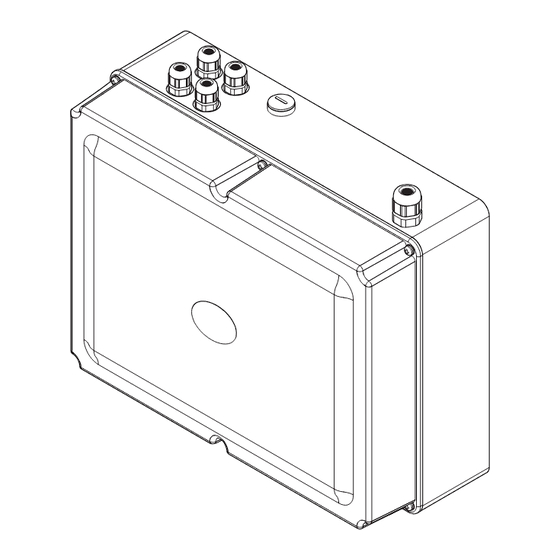
DIMeNsIONs 1. Rada Pulse Control Box 117 mm 300 mm 230 mm 2. Rada Pulse sensors 2.1 Rada Pulse 120/122 sensor 22 mm 68 mm 6 mm 84 mm 2.2 Rada Pulse 129 sensor (Rada Mounting Plate 129 - Optional Accessory) - Page 13 Note! The M6 fixing studs supplied allow the LR sensor to be attached through a wall to a maximum thickness of 165 mm. If longer M6 fixing studs are required, these will have to be purchased through your local supplier. 2.4 Rada Pulse 124, 125, 126 sensor 16 mm 9.5 mm to 25 mm...
- Page 14 3. solenoid Valves 3.1 sV1015 (HP) solenoid Valve 78 mm 127 mm 14 mm 3.2 sV2022 solenoid Valve 75 mm 18 mm 75 mm 55 mm 3.3 sV2028 solenoid Valve 85 mm 20 mm 72 mm 96 mm...
- Page 15 3.4 sV3022 solenoid Valve 90 mm 18 mm 82 mm 75 mm...
-
Page 16: Specifications
120 Va. main fuse: T 2.5 a h 250 V (Important! use only rada approved fuse, part no. 422.84) 10 x inputs suitable for pulse sensors. 10 x solenoid outputs, 12 V ac selV (5 fuses) - fused at 2.5 a for each pair. - Page 17 Activation distance: 0 mm to 50 mm depending on the reflectivity of the detected object. 2.4 Rada Pulse 124, 125 and 126 Ceiling sensor rada 124 for washbasin rada 125 for single urinal rada 126 for group urinal material: base and cover abs.
-
Page 18: Solenoid Valves
0.4 m 0.4 m extension cable - Optional Accessory 3.0 metres of sheathed cable and two 3m connectors. use to extend any rada pulse sensor to a maximum of 6.0 metres. 3. solenoid Valves General operating voltage (see note) 10.2 to 13.5 Volts ac. - Page 19 Min / Max Pressures: 20 to 1000 kpa (0.2 to 10 bar). Type: servo assisted. 3.3 sV3022 solenoid Valve Note! a maximum of 5 sV3022 solenoid Valves may be used on one rada pulse control system. supply Voltage: 12 V ac, 50/60 hz.
-
Page 20: Installation
Warning! do not connect the solenoid valves to mains voltage. Note! The Rada Pulse system control box can power a maximum of five SV3022 solenoid valves. These must be controlled by alternate power outputs on the pulse system control box, (e.g. -
Page 21: Install The Control Box
(0.75 mm Control Auxiliaries The control pcb has terminals to allow control of auxiliary items by the rada pulse system (e.g. pump, fan, lights and disinfection). Important! Do not connect mains voltage to the PCB Auxilliary Terminals. - Page 22 , disinfection connection to mains (refer to section: 'Description, power supply 4. Accessories, 4.1 Rada Pulse Relay Box') Transformer plug-in connections to solenoid Valves cover screws plug-in connections cover to pulse sensors Installation of the Rada Pulse Control Box...
-
Page 23: Install The Sensors
2. Install the sensors General The rada pulse sensors use the 12 V ac electrical supply provided by the transformer within the rada pulse system control box. Sensors should be fitted in a dry position, allowing access for adjustment or maintenance. -
Page 24: Rada Pulse129 Sensor
To prevent water ingress into the building fabric place a thin bead of silicone sealant around the top edge of the sensor (refer to illustration). make the connection between the 2 core cable and the rada pulse control box using the plug-in connector (supplied). - Page 25 129 sensor, making plate mounting plate fixing sure that the cable from the sensor screws (not supplied)
-
Page 26: Rada Pulse Lr Sensor
2.3 Rada Pulse lR sensor The lR sensor has been designed to be recessed or built within the wall. To allow for extra security the LR Sensor must be installed flush with the finished wall. Note! The lr sensor is the same size as a single electrical mounting box and the recommended method of recessing the lr sensor is to use an electrical box sinker Tool. - Page 27 11. Place the LR Sensor backplate/washers over the M6 fixing studs and secure with the nuts. 12. Grout around the lr sensor with hard setting compound. 13. make the connection between the 2 core cable and the rada pulse control box using the plug-in connector (supplied).
-
Page 28: Rada Pulse 124, 125 And 126 Ceiling Sensors
2.4 Rada Pulse 124, 125 and 126 Ceiling sensors Important! care must be taken to avoid installing system cables in close proximity to other electrical cables and devices as this may impair the function of the rada pulse system. in problematic installations the system cables should be installed within earthed (grounded) steel conduit. - Page 29 Installation of Ceiling sensor...
-
Page 30: Install The Solenoid Valves
3. Install the solenoid Valves 3.1 Rada sV1015 (HP) solenoid Valve Connect the pipework to the inlet/outlet fittings. For 15 mm compression connections: use the compression nuts and olives supplied. For 1/2" BsP union connections: Fit the flat-faced inserts (supplied) to the inlet/outlet fittings. -
Page 31: Sv2022/Sv2028 Solenoid Valve
3.2 sV2022/sV2028 solenoid Valve Important! The SV2022 and SV2028 Solenoid Valves must be fitted horizontally (with the solenoid coil at the top). connect the pipework to the inlet/outlet of the valve (refer to illustration). we recommend the use of union type fittings (not supplied) to ease removal of the valve if required. -
Page 32: Sv3022 Solenoid Valve
Important! These must be connected to alternate outputs of the rada pulse control box (e.g. 1, 3, 5, 7, 9). each fuse in the rada pulse control box supplies a single pair of outputs (e.g. fuse 1 = Valve 1 / Valve 2, fuse 2 = Valve 3 / Valve 4). -
Page 33: Tm Connectors
4. 3M Connectors The sensor cables on the pulse operating systems can be lengthened by using the 3M™ connectors included with the fixing pack. The cable to be joined must be to the same specification as the integral sensor cable (LAPP Unitronic LIYY). It is recommended that the total cable length should not exceed 6 metres. -
Page 34: Commissioning / Programming
12V ac ±... -
Page 35: Final Commissioning - Walk Test
Rada Pulse Relay Box (accessory) The auxiliary channels of the rada pulse control box must be programmed if a rada pulse relay box has been installed. refer to the rada pulse hand held programmer product manual. Final Commissioning - Walk Test for Pulse Ceiling sensors 124, 125 and 126, operate the sensor by body movement within the sensor target area (for adjustment refer to section: '2. -
Page 36: Maintenance
Always isolate the power supply before carrying out any work on the Rada Pulse system. when ordering spare parts, please state the product type, i.e. rada pulse, and identify the part name and number (refer to section: 'spare Parts'). - Page 37 Replacement Procedure - Transformer isolate the electrical supply to the control box. remove the cover from the control box. disconnect the electrical cable that connects the transformer to the pcb. unscrew the cable gland and carefully pull the electrical cable through it. Remove the fixing screws (4 off) that secure the transformer to the control box.
- Page 38 Replacement Procedure - PCB isolate the electrical supply to the control box. remove the cover from the control box. disconnect the electrical cable that connects the transformer to the pcb. make a note of the positions of the connections for the sensors and the solenoid valves.
- Page 39 Rada sV1015 (HP) solenoid Valve electrical connector solenoid coil if the solenoid valve fails to close when the power is disconnected, it needs cleaning: screw isolate the water supplies and relieve spring the pressure by operating an outlet. switch off the power. unscrew the...
- Page 40 sV2022/sV2028 solenoid Valves solenoid coil if the solenoid valve fails to close when the power is disconnected, it needs cleaning: isolate the water supplies and relieve electrical connector the pressure by operating an outlet. switch off the power and remove the nut and the washer which hold on the solenoid coil.
- Page 41 sV3022 solenoid Valve if the solenoid valve fails to close when washer the power is disconnected, it needs cleaning: solenoid coil isolate the water supplies and relieve electrical the pressure by operating an outlet. connector switch off the power and remove the nut and the washer which hold on the solenoid coil.
-
Page 42: Fault Diagnosis
(refer to the hand held programmer product manual). check that the sensor and/or solenoid connections on the pcb are pushed fully home and the connections on the sensor and/or solenoid are secure. -
Page 43: Spare Parts
2.5 amp 422.83 supply fuse (12 V) 400 ma T 422.84 mains input fuse (located in transformer, not shown) T 2.5a h 250 V (Important! use only rada approved fuse, part no. 422.84) 422.78 422.79 422.80 422.81 422.83... - Page 44 Rada Pulse 129 sensor 915.06 rada mounting plate 129 rada mounting plate 129: supplied with 2 x m5 x 12 mm stainless steel screws and 1 x 2.5 mm hexagonal wrench used to secure the rada pulse 129 sensor for extra fixing security.
- Page 45 Rada Pulse lR sensor 1640.033 lr sensor backplate assembly (LR sensor backplate, 2 x M6 x 175 mm fixing studs with fittings)
- Page 46 Rada sV1015 (HP) solenoid Valve 408.71 408.71 flat-faced inserts (2) 424.52 component pack 817.38 solenoid Valve (15 mm) 817.38 424.52 408.71 sV2022 and sV2028 solenoid Valve 422.90 coil 422.91 power connector 422.95 diaphragm (sV2022) 422.91 422.98 diaphragm (sV2028) 422.90 424.52 component pack 424.52...
- Page 47 sV3022 solenoid Valve 422.92 coil 422.96 diaphragm assembly 422.92 422.96...
-
Page 48: Customer Care
Spare Parts All functional parts of Rada products are kept for up to ten years from the date of fi nal manufacture. If during that period, our stock of a particular part is exhausted we will, as an alternative, provide an equivalent new product or part at a price equating to the cost of repair to the old, bearing in mind the age of the product.
Need help?
Do you have a question about the Pulse Series and is the answer not in the manual?
Questions and answers