Table of Contents
Advertisement
Quick Links
Advertisement
Table of Contents

Related Manuals for BEP Smart Battery Hub


Summary of Contents for BEP Smart Battery Hub
- Page 1 Smart Battery Hub User & Installation Manual v1.0...
- Page 2 Important BEP strives to ensure all information is correct at the time of printing. However, the company reserves the right to change without notice any features and specifications of either its products or associated documentation. Translations: In the event that there is a difference between a translation of this manual and the English version, the English version should be considered the official version.
-
Page 3: Table Of Contents
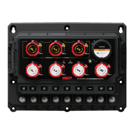
DESIGN ............................... 11 Things You Need ..........................11 Mounting Instructions ........................... 11 CONNECTIONS ..........................12 Smart Battery Hub Twin Engine ......................12 Smart Battery Hub Triple Engine......................13 Internal wiring overview ........................14 Temperature Sensor ..........................15 24 Hour Loads ............................. 15 Battery Charger Connections ....................... - Page 4 ORDERING INFORMATION ......................26 CE DELCARATION OF CONFORMITY ..................29 Table Of Figures Figure 1. SBH Smart Battery Hub Overview ......................6 Figure 2. Exploded Mounting View ......................... 11 Figure 3 Twin Engine Connections ......................... 12 Figure 4. Triple engine connections ........................13 Figure 5.
-
Page 5: General Information
Conditions of Sale. Warranty The BEP product warranty covers the Smart Battery Hub for the first five years after the purchase date, on the condition that the product is installed and used according to the instructions in this manual. Installation or use that does not comply with these instructions may result in under performance, damage or failure of the product and may void this warranty. -
Page 6: Overview
Overview Description BEP Smart Battery Hub is your all in one battery management system. Designed to simplify the installation of your battery management components. With state-of-the-art internal components combined with decades of refined software algorithms, the Smart Battery Hub delivers battery monitoring of all batteries including full state of charge calculation of the house battery with an advanced internal current sensor. -
Page 7: Led Indicators
Switch On Green Slow Voltage Sensitive Switch active Flash Green Rapid Configuration is being written to the Smart Battery Hub Flash Red Solid On Switch in manual override / not able to be controlled by software Red Flash Switch fault... -
Page 8: Usb Port
User Installation Manual USB PORT The USB port on the Smart Battery Hub allows system software updates and configuration files to be loaded from a USB Memory Stick. The Smart Battery Hub can also be used to update firmware on connected CZone®... -
Page 9: Nmea 2000
The Smart Battery Hub can be configured to react to data on the NMEA2000 network. This can be used to switch on or off the switches on the Smart Battery Hub itself, or it can be used to switch other modules on the CZone®... -
Page 10: Sleep Mode
Sleep Mode The Smart Battery Hub has an ultra-low current draw sleep mode, using less than 5mA of power while continuing to monitor the internal shunt for current draw on the house bank for state of charge calculating. Sleep mode is enabled automatically when certain criteria is met or can be manually activated through a circuit configured in the CZone®... -
Page 11: Installation
Once the SBH is in sleep mode, it will wake from any network traffic on the NMEA2000 bus. If there are no CZone control messages sent, the Smart Battery Hub will automatically go back to sleep once the CAN traffic goes away. -
Page 12: Connections
EN / BEP Smart Battery Hub User Installation Manual Connections Smart Battery Hub Twin Engine Port engine Port battery Starboard engine Starboard battery House loads House battery 24-hour house loads NMEA2000 network Main harness connector 10. External temperature sensor (optional) -
Page 13: Smart Battery Hub Triple Engine
EN / BEP Smart Battery Hub User Installation Manual Smart Battery Hub Triple Engine Port engine Port battery Centre engine Centre battery Starboard engine Starboard battery House loads House battery 24-hour house loads 10. NMEA2000 network 11. Main harness connector 12. -
Page 14: Internal Wiring Overview
EN / BEP Smart Battery Hub User Installation Manual Internal wiring overview Smart Battery Hub Twin Engine Figure 5. Twin engine internal wiring Smart Battery Hub Triple Engine Figure 6. Triple engine internal wiring = Voltmeter = Terminal = Shunt... -
Page 15: Temperature Sensor
NMEA2000 is with the Battery Temp PGN. If the house battery bank is not located in the Smart Battery Hub vicinity it is recommended to add an external temperature sensor. The external sensor can be fixed with screws, adhesive tape or cable tied to a loom. The external temperature sensor allows for a more accurate state of charge calculation when the battery is located away from the is Smart Battery Hub. -
Page 16: Connector Pin Out
EN / BEP Smart Battery Hub User Installation Manual Connector pin out The Smart Battery Hub main connector requires a DT06-12SA 12-way Deutsch connector. Figure 8. Connector Pin Out FUNCTION COLOR Signal interface White with Monitor external sensors and transmit data over... -
Page 17: Inputs And Outputs
Master status output The master status output is used to drive an external LED indicator and shows if the Smart Battery Hub is active or in Sleep mode. The status output is a switch to ground circuit and is designed to work with an LED with an externally fused power supply to the LED status indicator. -
Page 18: Switch Input And Si Input Wiring
EN / BEP Smart Battery Hub User Installation Manual Switch input and SI input Wiring Default configuration: Figure 9. Default Switch / SI Input Optional configuration example: Figure 10. Optional Switch / SI Input... -
Page 19: Settings
VSS settings. This is to protect the cranking batteries from sustained higher voltage of the lithium batteries for long periods when on shore power. The VSS settings for the Smart Battery Hub are configurable using the dipswitches below or the CZone Configuration Tool. -
Page 20: Dipswitches
CZone Configuration Tool. Leaving the CZone Enabled switch off will leave Smart Battery Hub in standalone mode. The SBH will transmit simple DC Status messages over NMEA2000 for each battery. In standalone mode, you will need to configure the house battery type and capacity via dipswitch 2. - Page 21 EN / BEP Smart Battery Hub User Installation Manual Example: Shows VSS functionality disabled for all engines, and CZone® functionality turned ON. Note: Dipswitch 2 Check Dipswitch 1 (No.8) for function of Dipswitch Dipswitch 2 Settings If dipswitch 1 has CZone® enabled ON, dipswitch 2 is used for the CZone® device address. This will allow for configuration of the device from the CZone Configuration Tool.
-
Page 22: Czone Configuration
USB to CAN adapter or via the Smart Battery Hub’s USB Port. CZone Configuration Tool Below shows the steps to create a basic configuration of the Smart Battery Hub, for advanced features, refer to the CZone Configuration Tool Instruction Manual found on the CZone Portal, https://downloads.czone.net. - Page 23 SBH. Configured circuits here will be automatically populated here on the circuits tab. To configure the battery monitoring features of the Smart Battery Hub, under the ‘Meters’ tab, ‘Add’ a new DC Meter. Give the new meter a name.
-
Page 24: Configuration Via Usb
For further feature instruction refer to CZone Configuration Tool Instruction Manual on the CZone Portal. Configuration via USB The configuration can be written to the Smart Battery Hub via a USB drive directly into the Smart Battery Hub. The process is slightly different for loading new configurations versus updating existing configurations already on the unit. -
Page 25: Multiple Smart Battery Hub Installations
EN / BEP Smart Battery Hub User Installation Manual Once the system configuration has been updated the following files will be created/updated: *.csv - A basic spreadsheet listing information about the system and modules connected to the network. CZone USB Result.txt - A text file describing the result of the last operation performed, as well as these instructions. -
Page 26: Specifications
EN / BEP Smart Battery Hub User Installation Manual Ordering Information Smart Battery Hub Part Numbers and Accessories Part Number Description 80-716-0030-00 BEP SMART BATTERY HUB TWIN ENGINE 80-716-0031-00 BEP SMART BATTERY HUB TRIPLE ENGINE 80-716-0032-00 SMART BATTERY HUB TEMP SENSOR (15m) -
Page 27: Dimensions
EN / BEP Smart Battery Hub User Installation Manual Dimensions W x H x D 363.5 x 275.4 x 159.5mm (14.310 x 10.841 x 6.280”) NMEA2000 PGN output Fluid Level, Pressure, Temperature, Battery Volts, State of Charge Monitoring Battery voltage, House current draw, House state of charge... -
Page 28: Figure 12. Dimensions
EN / BEP Smart Battery Hub User Installation Manual Figure 12. Dimensions... -
Page 29: Ce Delcaration Of Conformity
EN / BEP Smart Battery Hub User Installation Manual CE DELCARATION OF CONFORMITY...
Need help?
Do you have a question about the Smart Battery Hub and is the answer not in the manual?
Questions and answers