
Related Manuals for Vescent Photonics D2 Series


Summary of Contents for Vescent Photonics D2 Series
- Page 1 Quick Setup Guide Vescent Photonics, Inc. www.vescentphotonics.com 4865 E. 41 Denver, CO 80216 Phone: (303)-296-6766 Fax: (303)-296-6783...
-
Page 2: General Warnings And Cautions
WARNING Do not clean outside surfaces of any Vescent Photonics products with solvents such as acetone. Front panels on electronics modules may be cleaned with a mild soap and water solution. -
Page 3: Limited Warranty
Limited Warranty Vescent Photonics warrants this product to be free from defects in materials and workmanship for a period of one year from the date of shipment. If this product proves defective during the applicable warranty period, Vescent Photonics, at its option, either will repair the defective product without charge or will provide a replacement in exchange for the defective product. -
Page 5: Quick Setup Instructions
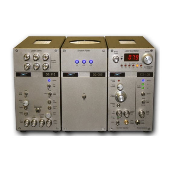
Vescent Photonics D2 Series Product Manual Quick Setup Instructions 1.1. Electronic Modules Initial Setup Place the three electronics modules (System Power, Laser Controller and Laser Servo) in a row as shown on the right (order is not important). On the back of the modules, attach the two power bridges across adjacent modules. -
Page 6: Laser Controller
Vescent Photonics D2 Series Product Manual Find the 6ft SMA / BNC cable and circular connector cable assembly. Plug the BNC end into the ERROR INPUT on the Laser Servo. Plug the SMA end into the Spectroscopy Module. Connect the circular connectors. - Page 7 Vescent Photonics D2 Series Product Manual 3. Take the key that was taped to back of the Laser Controller and place it in the back-panel Laser Enable keyhole and rotate the key 90 degrees (the key should be horizontal). 4. Now that both interlocks are enabled, flip the Laser switch into the “on” position. The green “Laser On”...
- Page 8 Vescent Photonics D2 Series Product Manual If you still cannot get the right signal strength, see the full instructions on aligning the spectroscopy module in the Spectroscopy Manual. 1.6. Locking the laser 1.6.1. Setting up the oscilloscope for locking. Connect a BNC cable from RAMP TTL on the back of the Laser Servo to the trigger input on your oscilloscope.
- Page 9 Vescent Photonics D2 Series Product Manual Optional: For long term frequency stability on side lock, monitor ERROR IN on the oscilloscope, open up the top of the Spectroscopy Module, and adjust the trimpot such that your desired lock point crosses 0V on the oscilloscope.
- Page 10 Vescent Photonics D2 Series Product Manual The laser will lock to where the error signal crosses zero voltage with a positive slope. If your desired lock point has a negative slope, flip the GAIN SIGN switch on the Laser Servo to invert the signal and make the slope positive.
Need help?
Do you have a question about the D2 Series and is the answer not in the manual?
Questions and answers