
Related Manuals for Vescent Photonics D2 Series


Summary of Contents for Vescent Photonics D2 Series
- Page 1 Reconfigurable Laser Servo Vescent Photonics, Inc. www.vescentphotonics.com 4865 E. 41 Denver, CO 80216 Phone: (303)-296-6766 Fax: (303)-296-6783 info@vescent.com...
-
Page 3: General Warnings And Cautions
WARNING Do not clean outside surfaces of any Vescent Photonics products with solvents such as acetone. Front panels on electronics modules may be cleaned with a mild soap and water solution. -
Page 5: Limited Warranty
Limited Warranty Vescent Photonics warrants this product to be free from defects in materials and workmanship for a period of one year from the date of shipment. If this product proves defective during the applicable warranty period, Vescent Photonics, at its option, either will repair the defective product without charge or will provide a replacement in exchange for the defective product. -
Page 6: Absolute Maximum Ratings
Absolute Maximum Ratings Note: All modules designed to be operated in laboratory environment Parameter Rating Environmental Temperature >15°C and <30°C Environmental Humidity <60% Environmental Dew Point <15°C... - Page 7 Vescent Photonics D2 Series Product Manual Reconfigurable Laser Servo Model No. D2-125 Document Revision: 5 1.1. Description The D2-125 Reconfigurable Laser Servo contains a tunable PI D loop filter for tight locking to an error signal. The error signal is either an amplified version of the Error Input signal (side-lock mode) or an amplified version of a demodulated Error Input (optional peak-lock mode).
- Page 8 Vescent Photonics D2 Series Product Manual optimized to a wide variety of plants and servo loops. With the Peak Lock option, the Laser Servo can demodulate a system-provided 4 MHz dither signal to enable slope-detection for locking to signal minima and maxima.
- Page 9 Vescent Photonics D2 Series Product Manual This option is recommend for Servoing PZT-based external-cavity lasers where the PZT amplifier (if used) does not have an offset knob. In this manual, sections that are only relevant to the Ramp Offset option are printed in green.
-
Page 10: Specifications
Vescent Photonics D2 Series Product Manual 1.2. Specifications Value Units Input and Output Impedance Ω ±10 Output Voltage Input Voltage Noise <5 nV/√Hz Max Input Voltage DC Level ±500 Max Input Voltage Signal Amplitude ±500 >10 Bandwidth -40 to +32... -
Page 11: Inputs, Outputs, And Controls
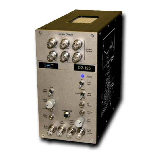
Vescent Photonics D2 Series Product Manual 1.3. Inputs, Outputs, and Controls Figure 1: Schematic drawing of the front and back panels. 1.3.1. Monitor Section Located at the top of the front panel, the monitor section contains 6 BNC outputs for monitoring various signals used by the Laser Servo. - Page 12 Vescent Photonics D2 Series Product Manual AC Error The AC ERROR monitors the same signal as the DC ERROR, except there is no low-pass filter and the signal is coupled through a high pass filter to remove DC components (< 10 Hz). It is designed for spectrum analysis and is also useful for coarse estimates of the laser line-width.
- Page 13 Vescent Photonics D2 Series Product Manual require further adjustment. When used with the D2-105 Laser Controller, the RF OUTPUT should be connected to the Laser Controller's RF INPUT to modulate the laser current. Error Input (BNC) This is the input for the error signal. In SIDE LOCK mode, the signal is amplified by 26 dB and summed with the DC OFFSET and DC OFFSET INPUT (back panel).
- Page 14 Vescent Photonics D2 Series Product Manual Servo Output The SERVO OUTPUT is a voltage output to control the frequency of the laser. When the Laser Servo is used with the D2-105 Laser Controller, the SERVO OUTPUT is connected to the CURRENT SERVO INPUT on the Laser Controller.
- Page 15 Vescent Photonics D2 Series Product Manual 1.3.3. Right Side Panel Figure 2: TOP: Picture of right-side panel. BOTTOM: schematic of the configurable transfer function and its user-controls.
- Page 16 Vescent Photonics D2 Series Product Manual The feedback loop is defined by the Gain vs Frequency plot shown above. ω , ω and ω define three zeros in the transfer function. ω and ω are the frequencies where the first and second integrators respectively switch from having integral gain to having proportional gain.
- Page 17 Vescent Photonics D2 Series Product Manual Figure 3: Certain rarely used controls are only accessible by removing the right- side panel, as shown in the figure above. Selector DIP Switch Array: Ramp->Aux / Ramp->Servo (2-position slider switch) This 2-position slider switch is only accessible by removing the right side panel (see above) and sets whether the ramp is applied to the SERVO OUTPUT or the AUXILIARY SERVO OUTPUT.
- Page 18 Vescent Photonics D2 Series Product Manual Aux: Bipolar / Aux: Unipolar (2-position slider switch) This 2-position slider switch is only accessible by removing the right side panel (see above) and sets whether the AUXILIARY OUTPUT SERVO is unipolar or bipolar. It is factory set to be bipolar so the auxiliary output can range from -12 V to +12 V.
- Page 19 Vescent Photonics D2 Series Product Manual Hold Settle Time Time Off Off Off 60 µs 150 µs On Off Off 125µs 300 µs Off On Off 250 µs 600 µs On On Off 500 µs 1.25 ms Off Off On 1 ms 2.5 ms...
- Page 20 Vescent Photonics D2 Series Product Manual Absolute Jump TTL (BNC) When asserted HIGH (5V) while in LOCK mode, ABSOLUTE JUMP takes the Laser Servo out of lock and conveys the negative of the voltage on LASER JUMP AMPLITUDE to the SERVO OUTPUT.
- Page 21 Vescent Photonics D2 Series Product Manual Ramp TTL Same as the front panel signal. The RAMP TTL is a trigger synchronous with the ramp. It is used to trigger an oscilloscope while sweeping the SERVO OUTPUT. Ramp IN / OUT The Laser Servo is shipped with the Ramp in MASTER MODE.
- Page 22 Vescent Photonics D2 Series Product Manual • DC OFFSET not adjusted properly. o When monitoring DC ERROR make sure you are not AC coupled on the oscilloscope! o When locking to spectroscopy, ramping fast through the transition can change the DC value on the scope (due to atom transit time through laser beam coupling to optical pumping rates).
Need help?
Do you have a question about the D2 Series and is the answer not in the manual?
Questions and answers