
Related Manuals for Vescent Photonics D2-110

Summary of Contents for Vescent Photonics D2-110
- Page 1 Spectroscopy Module Vescent Photonics, Inc. www.vescentphotonics.com 4865 E. 41 Denver, CO 80216 Phone: (303)-296-6766 Fax: (303)-296-6783...
-
Page 2: General Warnings And Cautions
WARNING Do not clean outside surfaces of any Vescent Photonics products with solvents such as acetone. Front panels on electronics modules may be cleaned with a mild soap and water solution. -
Page 3: Limited Warranty
Limited Warranty Vescent Photonics warrants this product to be free from defects in materials and workmanship for a period of one year from the date of shipment. If this product proves defective during the applicable warranty period, Vescent Photonics, at its option, either will repair the defective product without charge or will provide a replacement in exchange for the defective product. -
Page 4: Absolute Maximum Ratings
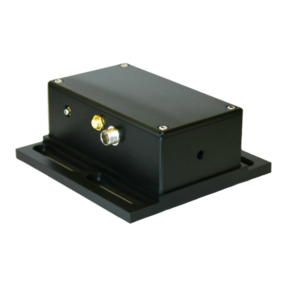
Absolute Maximum Ratings Note: All modules designed to be operated in laboratory environment Parameter Rating Environmental Temperature >15°C and <30°C Environmental Humidity <60% Environmental Dew Point <15°C... - Page 5 Vescent Photonics D2 Series Product Manual Spectroscopy Module Model No. D2-110 1.1. Description The spectroscopy module provides saturated absorption spectroscopy to atomic rubidium. It contains a rubidium absorption cell, TEC, balanced photodetector, and associated mirrors and beamsplitting optics. Nominally, it takes two 1% samples from the input beam. Temperature control stabilizes the number density of atoms in the cell, and a balanced photodetection circuit compensates for intensity drifts giving stable control over the lock point for side locking applications.
-
Page 6: Specifications
Vescent Photonics D2 Series Product Manual Fine steering adj. Fine steering adj. Focusing lens Focusing lens Input Input Input beamsplitter Input beamsplitter Signal Signal Cable Cable connector connector Signal SMA Signal SMA Ref. PD Ref. PD Course adj. Course adj. -
Page 7: Inputs, Outputs, And Controls
Vescent Photonics D2 Series Product Manual 1.3. Inputs, Outputs, and Controls Input Connector (8-pin circular) Power and temperature control signals from the Laser Servo are made through an 8-pin circular connector. The pin definitions (pin numbers are marked on the connectors) are listed below, where Rth and Rth_Rtn are the two ends of the thermistor. - Page 8 Vescent Photonics D2 Series Product Manual 5. At this point the beam should be going through the center of the input and output apertures on the module, the center of the 6 mm lens, and the second pick off should be impinging on the reference photodiode (see Figure 1).
- Page 9 Vescent Photonics D2 Series Product Manual 10. If the beam is visible on the card, center it with the course positioning controls. If not, repeat from Step 8. 11. Check to see that the beam is relatively well centered on the retro reflecting mirror at the end of the Rb cell.
- Page 10 Vescent Photonics D2 Series Product Manual 15. Adjust the trimpot until a desired lockpoint for sidelocking crosses zero volts (with oscilloscope connected to the ERROR INPUT monitor, or until an eyeball average of the hyperfine transitions lies near zero volts. This step determines how well the balancing circuit cancels intensity drifts.
Need help?
Do you have a question about the D2-110 and is the answer not in the manual?
Questions and answers