
Related Manuals for Vescent Photonics D2 Series


Summary of Contents for Vescent Photonics D2 Series
- Page 1 Offset Phase Lock Servo Vescent Photonics, Inc. www.vescentphotonics.com 4865 E. 41 Denver, CO 80216 Phone: (303)-296-6766 Fax: (303)-296-6783...
-
Page 3: General Warnings And Cautions
WARNING Do not clean outside surfaces of any Vescent Photonics products with solvents such as acetone. Front panels on electronics modules may be cleaned with a mild soap and water solution. -
Page 5: Limited Warranty
Limited Warranty Vescent Photonics warrants this product to be free from defects in materials and workmanship for a period of one year from the date of shipment. If this product proves defective during the applicable warranty period, Vescent Photonics, at its option, either will repair the defective product without charge or will provide a replacement in exchange for the defective product. -
Page 6: Absolute Maximum Ratings
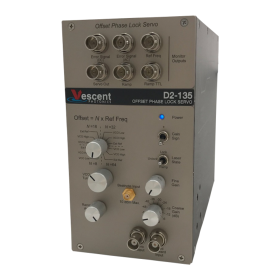
Absolute Maximum Ratings Note: All modules designed to be operated in laboratory environment Parameter Rating Environmental Temperature >15°C and <30°C Environmental Humidity <60% Environmental Dew Point <15°C... - Page 7 Vescent Photonics D2 Series Product Manual Offset Phase Lock Servo Model No. D2-135 Document Revision: 2 1.1. Description The D2-135 Offset Phase Lock Servo (OPLS) locks the frequency and phase of the input beat-note to a (multiple of the) reference frequency. The beat-note is typically generated by overlapping two lasers (a master laser and a slave laser), whose interference forms a beat-note, which is a measurement of the frequency difference (or offset) between the two lasers.
- Page 8 Vescent Photonics D2 Series Product Manual A schematic of the OPLS, along with the D2-150 Heterodyne module is shown in Figure 1.The key component in the OPLS is a phase-frequency detector (PFD). The PFD compares the phase and frequency of the divided-by-N beat-note to the reference frequency. The PFD outputs a signal proportional to the phase difference between the two input frequencies when there are no phase-slips between the two signals.
- Page 9 Vescent Photonics D2 Series Product Manual The D2-135-SMA requires an electrical signal input between 10 and -10 dBm of power. The D2-135-FC-800 includes a 10 GHz GaAs high-speed photo-detector for converting the input optical beat-note into a electrical beat-note. The maximum optical input power is 1 mW. Warning: input powers over 1mW of optical power can damage the OPLS.
-
Page 10: Specifications
Vescent Photonics D2 Series Product Manual 1.3. Specifications Value Units Min Offset Frequency <250 Min: 9, Typical: 10 Max Offset Frequency VCO drift ppm/°C PFD Noise -213 dBc/Hz (Integral/Prop. zero) 4,8,16,32,64,125,250,500 ω ω (Proportional/diff. zero) 16,32,64,125,250,500,1000,off ω (high freq. cutoff pole) 0.25, 0.5, 1,2,4,8,16,off... - Page 11 Vescent Photonics D2 Series Product Manual 1.4. Modes The OPLS operates in 12 different modes, controlled by the front-panel knob or with external inputs to the back-panel. These 12 modes select the value of the divide-by-N (N=8,16,32 or 64) and select between three states for the reference frequency (external input, internal VCO High, internal VCO Low).
-
Page 12: Inputs, Outputs, And Controls
Vescent Photonics D2 Series Product Manual 1.5. Inputs, Outputs, and Controls Figure 2: Schematic drawing of the front and back panels. 1.5.1. Monitor Section Located at the top of the front panel, the monitor section contains 6 BNC outputs for monitoring various signals used by the OPLS. - Page 13 Vescent Photonics D2 Series Product Manual Error Signal (HF) This is an unfiltered version of Error Signal (DC) that is four times smaller, and has a DC offset. 1.6 V +2.8 ∗θ When phase locked, the output is , where θ is the phase-error in degrees.
- Page 14 Vescent Photonics D2 Series Product Manual Gain Sign (two-position switch) The GAIN SIGN reverses the sign of the charge pump (CP) output. Effectively this selects whether the OPLS locks the slave laser to a frequency above or below the master laser frequency.
- Page 15 Vescent Photonics D2 Series Product Manual 1.5.3. Right Side Panel...
- Page 16 Vescent Photonics D2 Series Product Manual Figure 3: Schematic of the OPLS right-side panel, showing the configurable transfer function and its user-controls. The feedback loop is defined by the Gain vs Frequency plot shown above. ω , ω and ω...
- Page 17 Vescent Photonics D2 Series Product Manual Ramp Master / Slave (Not Shown) This jumper is only accessible by removing the right side panel and sets whether the ramp input is in master or slave mode. It is factory set to be in MASTER MODE. In SLAVE MODE (jumper off) the RAMP signal is generated externally and input through the back panel RAMP I/O port.
- Page 18 Vescent Photonics D2 Series Product Manual Pin 1 must be pulled to ground to enable computer control. Otherwise, all other pins on this cable are ignored and the OPLS state is set by the front-panel rotary switch. Pin 2 controls whether the gain sign is positive (pin 2 high) or negative (pin 2 low).
- Page 19 Vescent Photonics D2 Series Product Manual Ramp TTL Same as the front panel signal. The RAMP TTL is a trigger synchronous with the ramp. It is used to trigger an oscilloscope while sweeping the SERVO OUTPUT. Ramp IN / OUT The OPLS is shipped with the RAMP in MASTER MODE.
- Page 20 Vescent Photonics D2 Series Product Manual 1.6. Understanding Gain in the OPLS As described in Error Signal (DC) in 1.5.1 of page 12, the charge pump (CP) output is proportional to phase-error when phase-locked, but the slope is proportional to the value of N. This means that when N is increased, the same voltage on the CP monitor reflects twice as much phase-error.
Need help?
Do you have a question about the D2 Series and is the answer not in the manual?
Questions and answers