
Related Manuals for Movacolor MCTC


Summary of Contents for Movacolor MCTC
- Page 1 MCTC manual MCBalance Software version : 2.11.x Manual revision : rev.00 Language : ENG Date : February 2021...
- Page 2 Start-up & Login 4.2.1 Configuration wizard 4.2.2 Home screen 4.2.3 Help function 4.2.4 User levels 4.2.5 Customer Support -NEW- The MCTC production screen 4.3.1 Injection Molding mode 4.3.2 Extrusion mode 4.3.3 Batch mode 5 MCBalance operation MCBalance component configuration MCBalance load cell calibration Material files 5.3.1 Bulk density defined material -NEW-...
- Page 3 6.5.2 3PH hopper loader settings 6.5.3 Advanced loader settings 6.5.4 3PH electrical connections 6.5.5 Maintenance 7 Outputs APPENDIX A: MCTC Technical Specifications APPENDIX B: MCTC Dimensional drawing APPENDIX C: MCBalance dimensional drawing APPENDIX D: Electrical diagram APPENDIX E: Declaration of conformity...
- Page 4 1 Introduction Thank you for purchasing a Movacolor metering device. This manual is addressed to operators and qualified technicians taking care of the metering of dry additives to ensure correct use of the Movacolor dosing unit. This manual must be read before installing the dosing unit. Keep this manual in a place accessible for all operators.
- Page 5 Ensure that all parts are securely fixed to the extruder, injection molding machine or machine support. Always switch off the Movacolor control cabinet and disconnect the mains power plug from electrical power before performing maintenance. Dangerous voltages are present inside the control cabinet for up to 2 minutes after it has been switched off.
- Page 6 MC-Balance Load frame OPTIONAL Slide locking bolt (locking the slide-out position) Only supplied together with the optional slide mechanism OPTIONAL Slide frame 10. OPTIONAL Slide locking bar (locking the slide-in position) Only supplied together with the optional slide mechanism MCTC manual...
- Page 7 If LT motor is selected and HT motor is connected there will be less motor torque and this can influence the dosing. The motor type (LT/HT) and serial number of the motor can be found on the backside of the motor. MCTC manual...
- Page 8 • The surface structure of the material. The granular material and powder material has to be free flowing, non-static and not sticky. Movacolor offers mainly two dosing systems, the dosing cylinder and the feed screw. (for more information see chapter MCBalance dosing system / capacities).
- Page 9 (between the connection flange and the hopper; • mount the connection flange on the hopper by placing the four screws. Bearing (only used for dosing cylinder) Dosing auger tube (only used for dosing auger) MCTC manual...
- Page 10 3.3.4 MCBalance metering principle The Dosing Cylinder® of Movacolor combined with a stepper motor ensures that the additive output is accurate and regular. The neckpiece (a mixing chamber) is designed to blend the main material and the additive homogeneously. The most common mounting of the neckpiece is between the production machine and the main material hopper.
- Page 11 This will optimize the cleaning. dosing accuracy in relation to vibrations of the production machine; • Make sure that the complete unit is mounted; • horizontally levelled and fixed securely; • Assure proper grounding to control cabinet, neckpiece and dosing unit. MCTC manual...
- Page 12 Before switching on the unit for the first time, ensure the mains power voltage being applied is between 95 and 250Vac 50/60Hz; In case of a multi component system, the controller can be equipped with an additional CAN bus cable to interconnect between the MCTC and other MCBC’s;...
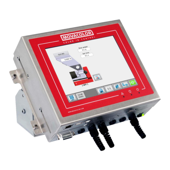
- Page 13 4 General operation The Interface 4.1.1 MCTC Touchscreen 1. Alarm LED 2. Input signal LED 3. Start LED (blinking = standby / waiting for start input, steady = motor running) External communication / network USB Port Load cell CAN bus cable...
- Page 14 The image below shows the MC-BC in a standard configuration. In multicomponent or remote setups, refer to chapter Multicomponent. 1. Load cell 2. CAN bus cable 3. Motor cable 4. Valve output for hopper loader 5. Mains power cable 6. Mains power switch 7. Mains power indicator MCTC manual...
- Page 15 Start-up & Login After switching on the mains power of the MCTC, the screen will remain black for about 15 seconds, followed by various loading screens. After about 90 seconds the home screen appears. When the unit is used for the first time, a Configuration Wizard appears.
- Page 16 4.2.4 User levels The MCTC controller has three user levels, each level has other rights to access or change functions and/or options. The three user levels are: Operator, Tooling and Supervisor For changing to another user level, press on the menu icon (left bottom corner) and the user button appears.
- Page 17 No data will be saved to the remote support servers. Once the MCTC is connected to the remote server, a 3-digit ID will be displayed on this screen. A support employee will ask for this ID as it's used to identify the MCTC.
- Page 18 The MCTC production screen 4.3.1 Injection Molding mode Material selection button. Through this button the material can be stored during production. Percentage of additive to be dosed in relation to the entered shot weight. Shot weight of the injection molding machine. Used for calculating the additive to be dosed.
- Page 19 Start/Stop button. When the button is colored green, the system is OFF (safe). In red condition the system is ON. Toggle button. With this button you can toggle between the normal and the detailed view. Actual RPM. Actual Hopper weight. 10. Actual tacho voltage. MCTC manual...
- Page 20 Tools menu. In this menu different settings can be made to the system. Check the “MCTC_Manual_General” for more detailed information. Start/Stop button. When the button is colored green, the system is OFF (safe). In red condition the system is ON. MCTC manual...
- Page 21 To manual fill the hopper, the manual fill button can be used. The EX knife gate valve will be open or the ME/MV system will be activated as long as the button is pressed. For more detailed information about hopper loading, see chapter MCBalance Loaders. MCTC manual...
- Page 22 The maximum limit value will be: 1,250 gr/sec; • The minimum limit value will be: 0,750 gr/sec. Calibration deviation: The maximum allowed deviation from the Calibration set point can be set with this Parameter. (For more information see chapter Material files) MCTC manual...
- Page 23 Batch mode menu (3) only available when production mode is set to batch In this menu some settings can be made for the batch mode. For more detailed information about this mode, please check the “MCTC_Manual_General” manual. MCTC manual...
- Page 24 • Place 500 gr. calibration weight on the Hopper and check the displayed weight. If the actual weight is not corresponding with the placed weight, perform a new load cell calibration. MCTC manual...
- Page 25 During production, the MCTC will check/adjust the curve so it matches the setpoint. The next time the machine is started it will use the adjusted curve.
- Page 26 • dosing percentage. The ideal situation is to choose the same settings as used during actual production, however when the output is too high and the learn function cannot be completed within one hopper filling, choose a lower capacity. MCTC manual...
- Page 27 During the calibration the unit is regulating to its set point. When this point is reached the calibration will be saved automatically. On the basis of this point a complete curve is made on bases of default pre- programmed curves. MCTC manual...
- Page 28 To go back to the production menu without selecting a material from the list press the cancel button. The standard Movacolor curve can be selected by pressing the “default material” button located below the material list. MCTC manual...
- Page 29 During operation the indicator above the material hopper will display LEARN or OK. During startup of production without using a pre-learned curve (see previous paragraphs) the indicator will show LEARN. This means the set motor RPM is calculated according to the default Movacolor material curves, which might not correspond to the used material bulk density.
- Page 30 Perform a weight check as described in the load cell calibration chapter; • Check the motor seal for abnormal wear out; • Replace the filter of the ME system. Yearly • Perform a load cell calibration as described in the load cell calibration chapter. MCTC manual...
- Page 31 The low level weight parameter generates a low-level alarm if the hopper is empty. 6.1.2 ME hopper loader settings On the MCTC the loader settings can be changed in the Loader Settings menu. High Level (1) Filling stops when the hopper weight reaches this level.
- Page 32 6.1.5 Compressed air requirements The ME loader system is driven by low-pressure compressed air and mounted directly on top of the hopper lid of the Movacolor dosing unit. The MCTC controls the operation of the ME loading system. Air pressure: 4 –...
- Page 33 This makes the MV system the most practical and user-friendly system for both powders and granules. 6.2.2 MV hopper loader settings On the MCTC the loader settings can be changed in the Loader Settings menu. High level (1) Filling stops when the hopper weight reaches this level.
- Page 34 This button can be used to fill the hopper manually. As long as the button is pressed, the loader will fill the hopper. Manual fill is only enabled when the MCTC is not running. Recommended settings for MV hopper loader •...
- Page 35 6.2.5 Compressed air requirements The MV loader system is driven by low-pressure compressed air and mounted directly on top of the hopper lid of the Movacolor dosing unit. The MCTC controls the operation of the MV loading system. Air pressure: 4 –...
- Page 36 Connection Nuts (M10) for hopper loader mounting Material inlet distance ring In case the EX frame is used for free flowing powder or micro granules (ø < 1mm) it is recommended to remove the material inlet ring. Material inlet distance ring MCTC manual...
- Page 37 6.3.2 EX hopper loader settings On the MCTC the loader settings can be changed in the Loader Settings menu. High High Level (1) The Highest level. If this level is reached a “High High level” event appears. High level (2) The level where the knife gate valve will be closed after a filling cycle.
- Page 38 This button can be used to fill the hopper manually. As long as the button is pressed, the loader will fill the hopper. Manual fill is only enabled when the MCTC is not running. Recommended settings for EX hopper loader (support frame): •...
- Page 39 The EX uses the valve output of the MCTC/BC white brown 6.3.5 Compressed air requirements The EX loader system is driven by low-pressure compressed air. The MCTC controls the operation of the EX loading system. Air pressure: 4 – 6 Bar...
- Page 40 This button can be used to fill the hopper manually. As long as the button is pressed, the loader will fill the hopper. Manual fill is only enabled when the MCTC is not running. Advanced loader settings (6) This button opens the advanced loader level menu.
- Page 41 Manual fill (7) This button can be used to fill the hopper manually. As long as the button is pressed, the loader will fill the hopper. Manual fill is only enabled when the MCTC is not running. MCTC manual...
- Page 42 The filter is hereby available. Make sure no granules or dust can get into the motor of the MFD. Maintenance of motor for blower The motor carbon brushes should be examined after 500 hours of operation, and if necessary be replaced. MCTC manual...
- Page 43 This button can be used to fill the hopper manually. As long as the button is pressed, the loader will fill the hopper. Manual fill is only enabled when the MCTC is not running. Advanced loader settings (6) This button opens the advanced loader level menu.
- Page 44 This button can be used to fill the hopper manually. As long as the button is pressed, the loader will fill the hopper. Manual fill is only enabled when the MCTC is not running. Recommended settings for 3PH hopper loader: •...
- Page 45 6.5.4 3PH electrical connections The 3PH loader comes with a separate valve cable. Prepare the right length of this cable (from MCTC/BC controller to the Hopper loader control box). • Connect the brown and white wire to connection block 10-11 of the hopper loader control;...
- Page 46 41 – 42 output CLOSED during fill time No action No Action Activation of blower loading sequence 41 – 42 output CLOSED during filling Activation of compressed air filter cleaning 41 – 42 output CLOSED during blowback time MCTC manual...
- Page 47 APPENDIX A: MCTC Technical Specifications Controls: Input: Set and actual % setting for injection molding and extrusion Extrusion control: By relay or tacho Injection molding control: Automatic metering time synchronization or by manual timer Manual speed and time setting Speed: Manual setting from 0,1 to 200 RPM max, in increments of 0,1 RPM.
- Page 48 APPENDIX B: MCTC Dimensional drawing MCTC manual...
- Page 49 APPENDIX C: MCBalance dimensional drawing MCTC manual...
- Page 50 APPENDIX D: Electrical diagram MCTC manual...
- Page 51 8600 DA Sneek The Netherlands www.movacolor.com Declare under our sole responsibility that the product: Product description : Dosing equipment Product designation : MCTC, MCBC In combination with : MCBalance, MCHighOutput, MCWeight, MCLiquid, MCPowder, MCHybrid, MCNexus, MCNumera Year : 2021 Identification...
- Page 52 MCTC manual...
Need help?
Do you have a question about the MCTC and is the answer not in the manual?
Questions and answers