
Related Manuals for Movacolor MC-TC


Summary of Contents for Movacolor MC-TC
- Page 1 MC-TC MCBalance Powder Manual 1.14.UK.01 Software version V1.14 Manual revision Date March 2014 MC-TC manual...
-
Page 2: Table Of Contents
8 Trouble shooting ___________________________________________________________ 37 APPENDIX A: MC-TC Wiring Diagram ____________________________________________ 38 APPENDIX B: Mechanical dimensions ___________________________________________ 39 APPENDIX C: Exploded view ___________________________________________________ 40 APPENDIX D: MC-TC Technical Specifications ____________________________________ 41 APPENDIX D: MC-TC. Declaration of Conformity _________________________________ 42 MC-TC manual... -
Page 3: Introduction
Movacolor cannot be held liable for any damage during transport. 1.4 Receipt Check the unit thoroughly upon receipt. Pass any remarks to the local agent or Movacolor within 8 days upon receipt of goods. MC-TC manual... -
Page 4: General Information
Before switching on the unit for the first time, ensure that the mains power voltage applied is between 95 and 250VAC. Always switch off the Movacolor control cabinet and disconnect the mains power plug from electrical power before performing maintenance. -
Page 5: Operation
3 Operation 3.1 The Interface MC-TC Touchscreen Alarm LED is lighted: alarm / warning Start LED blinking: motor is stand by / waiting for start signal Input LED is lighted: Start LED lighted: input signal is ON motor is running... - Page 6 MC-BC Blind controller Mains power indicator: ON / OFF Mains power switch: ON / OFF Motor Load cell CAN bus cable cable Mains power cable Valve output for hopper loader MC-TC manual...
-
Page 7: Start-Up & Login
3.2 Start-up & Login After switching on the mains power of the MC-TC, the screen will remain black for about 15 seconds, followed by various screens where the last is showing the software version. After about 90 seconds the home screen appears. -
Page 8: System Configuration
3.3 System Configuration For initial setup the MC-TC controller needs to be configured. The following settings are for the entire system and there for needs te be altered once. It is not possible to change these settings for each separate configured component. For component specific configuration (MCBalance, MCHigh Output, MCWeight) see the device specific chapters. - Page 9 Connect green to + VDC and yellow to the - side of the generator. The maximum voltage that can be applied to the MC-TC is 30 VDC. The tacho voltage has to be reduced to 30 VDC if the tacho generator has a higher voltage output than 30 VDC at the maximum extruder output capacity.
- Page 10 This IP-address has to correspond with the IP-address of your computer. Ask your network administrator for a unique address. System Configuration: Netmask Netmask for use in a network environment (TCP/IP protocol). (For example 255.255.255.0) When the Movacolor dosing system is part of a network, the controller must have a Netmask for accessing the TCP/IP network. System Configuration: Gateway Gateway address for use in a network environment (TCP/IP protocol).
- Page 11 Opens the group component configuration menu. Within this menu the type of dosing/measuring device is selected. Click the component icon to select the type of dosing equipment to be configured. MCBalance/ MCBalance MCHighOutput MCHighOutput MCWeight MCLiquid MCBalance Regrind Regrind Powder MC-TC manual...
-
Page 12: Material Curves
2. Press the material “name” button and enter a material description. 3. Enter the production settings, recommended is to use the same settings as will be used in the final production. For injection molding: the shotweight the dosing time dosing percentage MC-TC manual... -
Page 13: Selecting A Learned Material Curve
When more material curve calibrations have been made, a curve can be loaded to the device. To do this: 1. In a multi component setup, select from the home screen the unit to load the material 2. Press the material selection button 1 MCBalance material selection button MC-TC manual... -
Page 14: Save Data Function
Starting a new production run with a previous stored material calibration/speed is now possible, Press on the curve description (1) when the unit is activated. The “SAVE MATERIAL” screen appears. Enter a material description (max.10 positions) and press to store the material curve. MC-TC manual... -
Page 15: Recipe Function
3.5 Recipe function With the MC-TC it is possible to store the current production settings into a recipe. All production settings of all units will be stored within this recipe. An easy recall of this production settings is possible by loading the previous stored recipe. -
Page 16: Load / Edit A Recipe
3.5.3 Delete a recipe From the HOME screen, press the recipe button: Select the desired recipe by using the up and down buttons: To delete the selected recipe. To delete all recipes in the list at once. MC-TC manual... -
Page 17: Usb Menu
3.6 USB menu The MC-TC is equipped with a USB host port. This port can be used for production and configuration settings backup/restore and MC-TC software updates. For software updates, contact your local Movacolor representative. Your USB memory stick should be formatted FAT32. -
Page 18: Consumption Counters
Total counter, counting all consumed material by the unit . For MCWeight + MCBalance(s), the consumption counters display only the material fed through the MCWeight, not the complete total consumed by the extruder. For a grand total you need to summarize the totals of all units. MC-TC manual... -
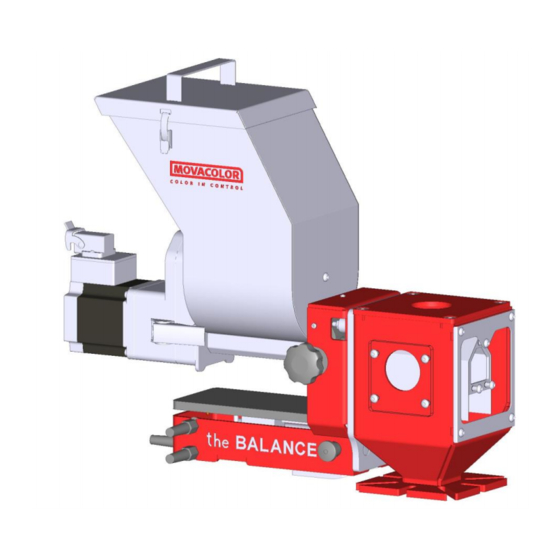
Page 19: Mcbalance Powder Operation
4 MCBalance Powder Operation 4.1 MCBalance Powder Component overview Stepper motor with gearbox Dosing twin spiral with seal Agitator Dosing tube with detachable thorn Neckpiece MC-Balance Load frame Slide frame Slide locking bolt (locking the slide-out position) Open insert Safety grid MC-TC manual... -
Page 20: Mcbalance Powder Motor
The MCBalance Powder dosing unit is standard equipped with the stepper motor 4A (HT) Stepper motor 4,5A (HT) with gearbox During configuration of the software, do not select the LT motor. This will cause influence the accuracy or the dosing or motor blocking. MC-TC manual... -
Page 21: Mcbalance Powder Dosing System
The motor can be disconnected with quick release clamps. When the motor is disconnected, the dosing spirals can be taken out without tools. To remove the agitator, the motor needs to be disconnected, and the safety grid needs to be removed (4 screws to be removed) MC-TC manual... -
Page 22: Reassembly Of The Mcbalance Powder Dosing System
Before assembly the spiral quick connection to the motor needs to be aligned. first position the spirals to the motor assembly before inserting in the hopper and dosing tube. 4.2.3 Exchange of dosing spiral type 4.2.4 Exchange of dosing tube MC-TC manual... -
Page 23: Mcbalance Powder Metering Principle
The neckpiece (a mixing chamber) is designed to blend the main material and the additive homogeneously. Movacolor has on stock a large range of machine neckpieces that usually make a perfect fit to the injection molding machine or extruder. -
Page 24: Mcbalance Powder Mechanical Installation
Motor cable Connect the loadcell connector to the MC-TC or MC-BC and tighten the locking screws gently. The motor connectors are equipped with a positioning notch and can be connected in one way only. Fixate the connector with the locking mechanism to prevent loosening of the connector due to vibrations. -
Page 25: Mcbalance Powder Loadcell Calibration
Place 500 gr. calibration weight on the Hopper and check the displayed weight If the actual weight is not corresponding with the placed weight, perform a new load cell calibration. In multicomponent setups it can be necessary to use the button to select the unit to be calibrated. MC-TC manual... -
Page 26: Mcbalance Powder Device Configuration
Time that MV needs for releasing 5 seconds default, MV only material into the hopper Alarm time Maximum filltime period 180s default Fill alarm mode Continue filling or stop filling ON = continue fill, OFF = stop fill MC-TC manual... - Page 27 When the maximum deviation message (Error 08) appears in the display of the controller it shows the measured deviation in percentage of the setpoint. Calibration deviation The maximum allowed deviation from the Calibration setpoint can be set with this Parameter. (For more information see chapter 3.4) MC-TC manual...
-
Page 28: Mcbalance Powder Production
The production data can be entered by touching the corresponding field 1. Ref.Curve/material Movacolor pre-programmed curve (dosing tool/granule type), or USER defined curve (material name) is displayed. (not available when recipe function is activated) 2. Color amount (%) 3. Shot weight (gr.) 4. - Page 29 3. Hopperweight ; Material weight in the hopper 4. Time; set dosing time (sec), when working TIMER input mode. The average dosing time (sec), when working in RELAY input mode. 5. Act. Time; count down of the actual dosing time (sec) MC-TC manual...
- Page 30 Act. Time; count down of the actual dosing time (sec) Please note that it is possible that the first dosing(s) are not sufficient, because of the cylinder filling with material. It takes some time to stabilize. MC-TC manual...
- Page 31 Production settings: The production data can be entered by touching the corresponding field. 1. Ref.Curve/material Movacolor pre-programmed curve (dosing tool/granule type), or USER defined curve (material name) is displayed. (not available when recipe function is activated) 2. Color amount (%) 3.
- Page 32 RPM of the dosing unit can be entered. Actual production data: During production the motor RPM, hopper weight, and tacho voltage (only in tacho function) will be displayed. MC-TC manual...
-
Page 33: Alarms
To reset an alarm / warning during production press to Stop dosing or / and confirm When an error occurs using the MC-TC, the display will indicate an error code and description. Together with the displayed error an output contact will be switched. -
Page 34: Warnings
Motor connection is not correct. - Make sure the motor is connected. - Check cable and connectors for damage. “Loadcell connection failure” Error 102 -Load cell connection is not correct. -Load cell connector is not connected to the controller. MC-TC manual... -
Page 35: System Performance
Changing more production parameters during production within 10 seconds after each other will cause the MC-TC regulation to reset. This is necessary for the system to adjust quickly to these big changes in the settings. ... -
Page 36: Outputs
Status = OFF Remark: In case of alarm, the alarm output (OUT-1) is switched and the system is stopped. This also switches output OUT-2 AUX Output (OUT-3) (mainboard software version S8H3 and higher) Normally open contact, connection 41 and 42 MC-TC manual... -
Page 37: Trouble Shooting
2. Extreme vibrations and shocks to the system. 3. Check if there is no obstruction to the weighing frame. 4. Check in case of use of an automatic hopper loader if the hoses are connected in the right way. MC-TC manual... -
Page 38: Appendix A: Mc-Tc Wiring Diagram
APPENDIX A: MC-TC Wiring Diagram MC-TC manual... -
Page 39: Appendix B: Mechanical Dimensions
APPENDIX B: Mechanical dimensions MC-TC manual... -
Page 40: Appendix C: Exploded View
APPENDIX C: Exploded view MC-TC manual... -
Page 41: Appendix D: Mc-Tc Technical Specifications
APPENDIX D: MC-TC Technical Specifications Controls: Set and actual % setting for injection molding and extrusion Extrusion control by relay or tacho Injection molding control Automatic metering time synchronization or by manual timer Manual speed and time setting Speed: Manual setting from 0,1 to 200 RPM max, in increments of 0,1 RPM. -
Page 42: Appendix D: Mc-Tc. Declaration Of Conformity
APPENDIX D: MC-TC. Declaration of Conformity DECLARATION OF CONFORMITY (According to 2006/42/EC) Manufacturer’s name MOVACOLOR BV Address P.O. Box 3016 8600 DA Sneek The Netherlands Declare under our sole responsibility that the product: Name Movacolor Model MC-TC 20….. Year ……………….
Need help?
Do you have a question about the MC-TC and is the answer not in the manual?
Questions and answers