Advertisement
Quick Links
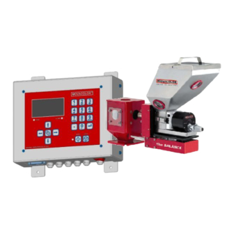
MC-BALANCE Quick Reference 4.0 UK.00
Part 1: Operation Reference
For more detailed information please consult the User Manual
Input LED is lighted:
input signal is ON
Alarm LED is lighted:
alarm / warning
Arrow left / right:
Scroll through menus
Enter / scroll / exit MENU
Arrow up / down:
Scroll through parameters
Load cell
External communication /
Network
Start input cable
Motor cable
GENERAL
1.
Terminal software version V0.08.
2.
Operation software version V4.0, production date April 2008.
3.
Connect motor and load cell before switch on the controller.
4.
All changes have to be confirmed with
START UP
Directly after switching ON the main power of the MC-Balance, the software versions will be displayed.
Alphanumerical
buttons:
Set values /
descriptions
Stop:
Stop unit
Start:
Start unit
Start LED blinking:
motor is stand by / waiting for start signal
Start LED lighted:
motor is running
Mains power switch: ON / OFF
Mains power cable
Output for:
-Alarm
-Warning
Valve output
-Running
for hopper loader
LOGIN <menu>
The MC-Balance has 3 user levels defined:
User Level
1.
Operator
2.
Tooling
3.
Supervisor
Key lock: (un)locked. No changes can be made in the settings. The keyboard can be (un)locked by the supervisor.
For changing to an other user level, enter the LOGIN menu and fill in the password (4 numerals) and confirm.
Login for Operator is 0000. The passwords for the other two user levels are defined by the supervisor.
Enter:
When entering a wrong password, user level will be set automatically to operator level.
Confirm settings
In OPERATOR LEVEL the following
PRODUCTION / HOPPER LOADER / LOGIN.
PRODUCTION <menu>
The following parameters can be seen in the production screen, depending on operation or settings, (made in supervisor mode):
Injection molding
Prod Job:
Name of the production Job
Set speed:
Rotating speed of the motor [RPM mode]
Dos. Time:
Dosing time (sec.)
Material:
Name of material calibration
Color%:
Color amount (%)
Shot wth:
Shot weight (gr.)
Test:
Select Test, select YES and confirm
Test time in extrusion mode is 30 seconds.
Production (Motor On/Off)
Press
to start production, the question appears Fill cylinder? YES/NO. YES means that the dosing cylinder will be filled. press
stop production. When the unit is started, the actual production data will be shown.
The start LED blinks when the unit is waiting for an input signal. The unit is dosing if the Start LED lights continuously.
Regulation mode: AUTO / MANUAL. In the MANUAL mode can be run with fixed RPM. The regulation is frozen.
HOPPER LOADER <menu>
The following parameters can be seen in the production screen, depending on operation or settings (made in supervisor mode):
In this menu all the hopper loader parameters can be set.
ME hopper loader (Movacolor hopper loader operated by compressed air)
ME system :
ME fill time:
ME alarm time:
ME alarm mode:
Manual fill:
MV hopper loader (Movacolor hopper loader operated by vacuum)
MV system:
MV fill time:
MV empty time:
MV fill cycles:
MV alarm cycles:
MV alarm mode:
Manual fill:
EX hopper loader (Support frame for external hopper loader)
EX system:
Alarm time:
Alarm mode:
Manual fill:
Access level
production settings / hopper loader settings
same as operator & additional material calibrations / job functionality / weight check / consumption /
alarm history / event log.
same as tooling & additional system configuration / alarm configuration / file management /
load cell calibration.
menus are available:
Extrusion
Prod Job:
Name of the production Job
Set speed:
Rotating speed of the motor [RPM mode]
[Timer mode]
Max. tacho: Maximum tacho voltage (V)
Material:
Name of material calibration
Color%:
Color amount (%)
Ext. cap:
Maximum extruder capacity (kg/hr)
. The unit will run with the set parameters.
Enable / disable ME hopper loader.
Fill time (sec.) after the weight is above the hopper fill weight (CONFIG.) again
Alarm time (sec.) Time between hopper empty weight (CONFIG) and
start of alarm, alarm time > fill time.
ME hopper loader is ON / OFF during fill alarm.
Yes = start filling immediately;
No = Stop filling immediately.
Enable / disable MV hopper loader.
Fill time (sec.)
Empty time (sec.) of MV loader before the next cycle.
Number of additional fill cycles after the weight is above the hopper fill weight again
Number of total fill cycles until fill alarm appears if hopper weight stays to low.
MV hopper loader is ON / OFF during fill alarm.
Yes = start filling immediately;
No = Stop filling immediately.
Enable / disable the Support frame system.
Alarm time (sec.) Time between hopper empty weight (CONFIG) and
start of alarm.
EX hopper loader is ON / OFF during fill alarm.
ON
= The system stays activated during a filling alarm.
OFF
= The system will be deactivated during a filling alarm.
Yes = starting filling immediately;
No = stop filling immediately
to
(On / Off)
(0,0-99,9 sec.)
(1,0-99,9 sec.)
(On / Off)
(0,0-99,9 sec.)
(0,0-99,9 sec.)
(0-99)
(0-99)
(1,0-99,9 sec.)
Advertisement

Related Manuals for Movacolor MC-BALANCE


Summary of Contents for Movacolor MC-BALANCE
- Page 1 = The system stays activated during a filling alarm. START UP = The system will be deactivated during a filling alarm. Directly after switching ON the main power of the MC-Balance, the software versions will be displayed. Manual fill: Yes = starting filling immediately;...
- Page 2 PRODUCTION <menu> Tooling / Supervisor level For initial setup the MC-Balance controller needs to be configured in the SYSTEM menu once. Depending on the settings, some parameters will be (in)visible in case they are not relevant. The following EXTRA parameters are displayed in the production screen when logged in as Tooling / supervisor...
- Page 3 The alarm history can be reset by the supervisor. When a problem occurs using the MC-Balance , the display will indicate an error code and description. Also the alarm LED lights up. Together with the displayed error an output contact can be switched.
- Page 4 ELECTRICAL INSTALLATION Input signal to the MC-Balance can be made in the following ways, in accordance with the configuration. Potential free contact Potential contact Tacho [Min 18VDC to Max.30VDC] 12 = Yellow 13 = Green INP1 + 24Vdc INP1 14 = White 15 = Brown [Min 0VDC to Max.
Need help?
Do you have a question about the MC-BALANCE and is the answer not in the manual?
Questions and answers