
Related Manuals for Meler PS20 NON STOP


Summary of Contents for Meler PS20 NON STOP
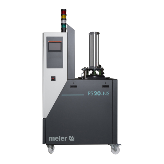
- Page 1 GLUING SOLUTIONS ADHESIVE INSTRUCTIONS MANUAL MELTER PS20 NON STOP MA-5060-GBR 210220...
- Page 2 The specifications and information contained in this manual may be modified without prior notice. This manual is a translation of the original that was written by Focke Meler Gluing Solutions, S. A in spanish language. If there is any discrepancy between the different versions of this manual, the original written in the spanish language shall prevail.
-
Page 3: Table Of Contents
TABLE OF CONTENTS MA-5060-GBR PS20 NON STOP DRUM UNLOADER MANUAL TABLE OF CONTENTS 1. SAFETY GUIDELINES General Symbols Mechanical components Electrical components Hydraulic components Pneumatic components Thermal components Materials Noise emission declaration Intended use Limited use 2. INTRODUCTION Description Intended use... - Page 4 FOCKE MELER GLUING SOLUTIONS TABLE OF CONTENTS Contents Mounting the equipment Electrical power connection Pneumatic connection Hose and applicator connection External I/O connections Temperatures ok External ON/OFF External Standby Low level (optional) ON/OFF Status Adhesive bag nealy empty Adhesive bag empty...
- Page 5 TABLE OF CONTENTS MA-5060-GBR PS20 NON STOP DRUM UNLOADER MANUAL Example of Programming for activation, deactivation and standby 4-15 Setting the security password 4-16 Set working temperature 4-17 Pumping speed control 4-19 Select signal “INTERNAL” 4-21 Select signal “EXTERNAL“ 4-21...
- Page 6 FOCKE MELER GLUING SOLUTIONS TABLE OF CONTENTS Pump maintenance 6-10 Inspecting for leaks 6-10 Motor-gear maintenance 6-10 Cleaning the motor fan 6-10 Checking the lubricant 6-10 Recommended lubricants 6-11 Thermostats maintenance 6-11 Air dryer filter maintenance 6-12 7. TECHNICAL CHARACTERISTICS...
-
Page 7: Safety Guidelines
SAFETY GUIDELINES MA-5060-GBR PS20 NON STOP DRUM UNLOADER MANUAL 1. SAFETY GUIDELINES General The information contained in this section applies not only to everyday equipment operation, but also to any procedure carried out on it, whether for preventive maintenance or in the case of repairs and the replacement of worn out parts. -
Page 8: Mechanical Components
FOCKE MELER GLUING SOLUTIONS SAFETY GUIDELINES Mechanical components The hot-melt installation, which is installed to this device, requires moving parts that can cause damage. Use the equipment correctly, and do not remove the safety guards while the equipment is in operation; prevent the risk of possible entrapment due to moving mechanical parts. -
Page 9: Thermal Components
Safety Information Sheet of the adhesive. Materials Meler systems are designed for use with hot-melt adhesives. They should not be used with any other type of material, and especially not with solvents, which may cause personal injury or damage to internal system components. -
Page 10: Intended Use
Note: Do not modify the equipment or use components that were not supplied by Meler. For any modification of a component of the equipment or part of the installation, you must firstly consult the After-Sales Service... -
Page 11: Introduction
In this manual you will find information about the installation, use and main- tenance of the hot-melt adhesive melter in meler’s Non Stop drum unloader, hereinafter PS20 Non Stop. The PS20 Non Stop serie includes the 50 range of hot-melt adhesive melters. -
Page 12: Description
Limited use PS20 Non Stop must be used in the manner in which they are intended, and never under the following conditions: • Used with materials that may represent safety or health hazards when heated. -
Page 13: Identifying The Melting Equipment
INTRODUCTION MA-5060-GBR PS20 NON STOP DRUM UNLOADER MANUAL pumping system have been activated by the operator (on the front panel with the ON/OFF button). The next, the temperatures pre-set for every element (platen, hoses and applicators) have been reached and the last, the delay time pre-set, until the pumping system starts, have been over. -
Page 14: Main Components
FOCKE MELER GLUING SOLUTIONS INTRODUCTION Main components 1. Touchscreen. 2. Access door to the electronic section and connections. 3. Tank access cover. 4. Main power switch. 5. Electrical connection. 6. Unit transport wheels. 7. Hose-applicator electrical connections. Right side or rear placed. - Page 15 INTRODUCTION MA-5060-GBR PS20 NON STOP DRUM UNLOADER MANUAL...
-
Page 16: Optional Equipment
FOCKE MELER GLUING SOLUTIONS INTRODUCTION Optional equipment To increase the performances of the machine it is possible to improve it with the following options: • Pneumatic by-pass valve pressure control system (VP). • Double pressure solenoid valve control system (DP). -
Page 17: Double Pressure Solenoid Valve Control System (Dp)
INTRODUCTION MA-5060-GBR PS20 NON STOP DRUM UNLOADER MANUAL Double pressure solenoid valve control system (DP) This solenoid valve has two air-inputs and one air-output. When the solenoid valve is not activated, the pressure to the bypass valve is equal to the net pressure supplied to the melter. At the moment this device is activated, air at a regulated pressure is introduced into the bypass valve. - Page 18 FOCKE MELER GLUING SOLUTIONS INTRODUCTION This page is intentionally left blank.
-
Page 19: Installation
Introduction The PS20 Non Stop melters are delivered with all the materials necessary for their installation. However, some components must be provided by the user himself, according to the location and connections in each particular installa- tion: •... -
Page 20: Electrical Consumption
FOCKE MELER GLUING SOLUTIONS INSTALLATION Electrical Consumption In order to install a PS20 Non Stop melter, we should take into consideration the total consumption of the installation, including the consumption of the installed hoses and applicators. Before connecting, make sure that the voltage that is being connected to the melter is the correct one appearing on the equipment’s characteristics plate. -
Page 21: Other Factors
• Connector for external I/O (included on the power card). Mounting the equipment The PS20 Non Stop melting equipment are equipped with wheels for their easy transport and positioning near the main machine. The four wheels turn 360°, and two are equipped with brakes. To move the... -
Page 22: Electrical Power Connection
FOCKE MELER GLUING SOLUTIONS INSTALLATION Electrical power connection PS20 Non Stop melters are designed to be connected to the electrical power supply in one possible way, depending on their power consumption: • 3-phase 400 VAC with neutral. A good ground connection is required in all cases. -
Page 23: Hose And Applicator Connection
PS20 Non Stop melters use standard Meler components. The entire range of Meler hoses and applicators may be connected to this equipment. Up to four hose-applicator outputs may be connected to PS20 Non Stop sys- tem melters, depending on the number of pumps installed. -
Page 24: Temperatures Ok
FOCKE MELER GLUING SOLUTIONS INSTALLATION • External Standby_control input from the standby mode, from a non-voltage contact. The standby function is connected with a closed contact; an open contact disconnects it. • Low level_ contact no- voltage output that connects the main machine (or to a warning light tower) the adhesive level in the tank has reached the minimum limit (optional). -
Page 25: External On/Off
INSTALLATION MA-5060-GBR PS20 NON STOP DRUM UNLOADER MANUAL External ON/OFF 1. If only this signal will be connected, use a 0.5 mm two-wire cable. 2. Open the door of the electrical cabinet as far as possible. Thread the power cord (Ø4-8 mm) through the electrical cable gland Pg13, making sure that the cord reaches the terminal blocks where that signal has to be connected. -
Page 26: On/Off Status
FOCKE MELER GLUING SOLUTIONS INSTALLATION 4. Make sure that the cables are firmly attached by the terminal screws. 5. Make sure that the cable is well connected and that its path through the electrical cabinet presents no risks of snagging, being cut or any other accidental deterioration. -
Page 27: Adhesive Bag Empty
INSTALLATION MA-5060-GBR PS20 NON STOP DRUM UNLOADER MANUAL Adhesive bag empty If only this signal will be connected, use a 0.5 mm two-wire cable. 2. Open the door of the electrical cabinet as far as possible. Thread the power cord (Ø4-8 mm) through the electrical cable gland Pg13, making sure that the cord reaches the terminal blocks where that signal has to be connected. -
Page 28: Motor Speed Set Point Reference
FOCKE MELER GLUING SOLUTIONS INSTALLATION 3. Insert the wires in XP11 and XP12 terminal blocks and tighten them with the fixing screws. The terminal block is double so you must to connect every wire in a free hole of the terminal block. It has no polari- ty so it doesn’t matter the place you connect them. -
Page 29: Touch Screen Navigation
TOUCH SCREEN NAVIGATION MA-5060-GBR PS20 NON STOP DRUM UNLOADER MANUAL 4. TOUCH SCREEN NAVIGATION The touch screen has 5 main tabs. At the same time inside the main thumbs there are some other menus. • Thumb A : ENTER – Screen 1 –... - Page 30 FOCKE MELER GLUING SOLUTIONS TOUCH SCREEN NAVIGATION A - Enter B - Internal Temperature C - External Temperature D - Pump E - Tank To screen 2 Screen Intro 2 To screen PROGRAM CONF. To screen DATE CONF. To screen 3 To screen 1 Screen PROGRAM CONF.
- Page 31 TOUCH SCREEN NAVIGATION MA-5060-GBR PS20 NON STOP DRUM UNLOADER MANUAL Screen DATE CONFIGURATION To screen 2 Screen Intro 3 To screen 4 To screen 2 Screen Intro 4 To screen 3 To screen Intro 5...
- Page 32 FOCKE MELER GLUING SOLUTIONS TOUCH SCREEN NAVIGATION Screen Intro 5 PASSWORD ENABLED To screen 2...
- Page 33 TOUCH SCREEN NAVIGATION MA-5060-GBR PS20 NON STOP DRUM UNLOADER MANUAL To screen EXTERNAL SIGNAL PUMP 1 If the equipment has 2 pumps to screen EXTERNAL SIGNAL To TºEXT screen 1 PUMP 2 Screen EXTERNAL SIGNAL PUMP 1 / PUMP 2...
- Page 34 FOCKE MELER GLUING SOLUTIONS TOUCH SCREEN NAVIGATION To screen PREMELTING To screen AIR INJECTION Screen PREMELTING To screen TANK Screen AIR-INJECTION To screen TANK...
-
Page 35: Equipment Configuration
TOUCH SCREEN NAVIGATION MA-5060-GBR PS20 NON STOP DRUM UNLOADER MANUAL Equipment configuration Parameters The machine can be configured 10 parameters. This is entered by the numeric display: 1. Overtemperature When the set-point temperature is exceeded by a value between 10 and 30, switch off the machine. -
Page 36: Activation Standby Because Of Motor Off
FOCKE MELER GLUING SOLUTIONS TOUCH SCREEN NAVIGATION 3. Activation standby because of motor OFF After a while without use of the motor, the equipment goes into standby. This time is programmed and can vary between 1 and 60 minutes. It is activated with the tab ON / OFF. -
Page 37: Air Injection Time
TOUCH SCREEN NAVIGATION MA-5060-GBR PS20 NON STOP DRUM UNLOADER MANUAL 5. Air injection time The time during which air goes in and goes out. To screen GAS INJECTION To numeric screen The numeric display appears. Enter a value and push “ENTER”. -
Page 38: Alarm Time In The Air Injection
FOCKE MELER GLUING SOLUTIONS TOUCH SCREEN NAVIGATION 7. Alarm time in the air injection If air injection is activated and lid of the tank is opened, a time goes until the alarm is activated (the red light switches on). To numeric screen The numeric display appears. -
Page 39: Timeout
TOUCH SCREEN NAVIGATION MA-5060-GBR PS20 NON STOP DRUM UNLOADER MANUAL 9. Timeout If the premelting is enabled and the level detector is detecting adhesive, the “Timeout” position is the time in seconds since this position until the compu- ter is disabled premelting. -
Page 40: Programming The Time
FOCKE MELER GLUING SOLUTIONS TOUCH SCREEN NAVIGATION Programming the time 1. Programming current day and hour To DATE CONF. DATE AND TIME scrren appears. To numeric screen The numeric display appears. Enter a value and push “ENT”. Repeat the same process to change the month, day, hour and minute. Finally make tab “CHANGE”. -
Page 41: Programming Activation / Deactivation Equipment
TOUCH SCREEN NAVIGATION MA-5060-GBR PS20 NON STOP DRUM UNLOADER MANUAL 2. Programming activation / deactivation equipment For each day of the week it is possible to program a start time and a deactiva- tion. This setting is enabled or disabled using the ON / OFF. -
Page 42: Programming Activation / Deactivation Standby Function
FOCKE MELER GLUING SOLUTIONS TOUCH SCREEN NAVIGATION Finally turned on or off by the tab programming ON/OFF. ON / OFF 3. Programming activation / deactivation standby function For each day of the week it is possible to program an activation and deacti- vation time. -
Page 43: Example Of Programming For Activation, Deactivation And Standby
TOUCH SCREEN NAVIGATION MA-5060-GBR PS20 NON STOP DRUM UNLOADER MANUAL Example of Programming for activation, deactivation and standby We want the unit to operate weekly with the following sequence: • Monday ON 09:00 h -> • Tuesday STANDBY ON 17:00h ->... -
Page 44: Setting The Security Password
FOCKE MELER GLUING SOLUTIONS TOUCH SCREEN NAVIGATION Setting the security password When the unit’s password is enabled, the operator can view the operating data on the menu’s various screens, but they cannot make changes. The main screen shows a red padlock, to indicate that the password is enabled and a green icon to show that it is disabled. -
Page 45: Set Working Temperature
TOUCH SCREEN NAVIGATION MA-5060-GBR PS20 NON STOP DRUM UNLOADER MANUAL Set working temperature To get a proper working of the equipment is essential to select the appropriate working temperatures. These temperatures depend on the softening point of the adhesive. Warning: The temperature selected for the bottom of the tank MUST NOT EXCEED in 15º... - Page 46 FOCKE MELER GLUING SOLUTIONS TOUCH SCREEN NAVIGATION To establish the applicators and hoses temperatures select “T. EXT”. Within of this tab it can access to Screen 1, and Screen 2. Screen 1 shows the applicator and hose temperature 1 and 2.
-
Page 47: Pumping Speed Control
TOUCH SCREEN NAVIGATION MA-5060-GBR PS20 NON STOP DRUM UNLOADER MANUAL The right column shows the actual temperature and the left column the se- lected temperature. Set Temperature Real Temperature It can activate and desactivate the manifolds, applicators, hoses pushing the ON/OFF tab. - Page 48 FOCKE MELER GLUING SOLUTIONS TOUCH SCREEN NAVIGATION Three requirements must be comply to pumping: 1. Pumping option must be ON (select on the screen with option ON/OFF. 2. The temperatures selected for each element (tank, grid, manifold, applicators and hoses) have been achieved.
-
Page 49: Select Signal "Internal
TOUCH SCREEN NAVIGATION MA-5060-GBR PS20 NON STOP DRUM UNLOADER MANUAL Set the ON/OFF “EXTERNAL”. Now, it can select internal or external setpoint. Select signal “INTERNAL” Select “INTERNAL”.Click to introduce the speed value. The numeric display appears. Enter a value between 0 and 100 and push “EN- TER”. - Page 50 FOCKE MELER GLUING SOLUTIONS TOUCH SCREEN NAVIGATION The screen EXTERNAL SIGNAL PUMP 1 or EXTERNAL SIGNAL PUMP 2 appears. The table with the values you want for the complete application. The numerical screen appears when you mark each tab. Enter a value between 0 and 100 and press “ENTER”.
-
Page 51: By-Pass Valve Regulation
TOUCH SCREEN NAVIGATION MA-5060-GBR PS20 NON STOP DRUM UNLOADER MANUAL By-pass valve regulation The pumping system using a geared pump provides a constant flow of adhesi- ve, according to the pump’s rotational speed. In this type of system, the pressure generated by the pump is the result of the retentions found on the circuit (the length and diameter of the hose, elbows in the connectors, the diameters of the nozzle outputs, etc.) and the adhesive... -
Page 52: Switch Off The Melter
PS20 Non Stop melting equipment ensures a dry environment thanks to the addition of an air-drying system to these models, which provides a level of de- humidification above 99.98%. This guarantees that the adhesive is preserved without premature reticulations inside the applicator unit. -
Page 53: Regulating Pushing Pressure
TOUCH SCREEN NAVIGATION MA-5060-GBR PS20 NON STOP DRUM UNLOADER MANUAL Cylinder solenoid valve Regulator 1 Regulator 2 Discharge solenoid valve Pressure gauge Input solenoid valve Pressure gauge Relief valve 0.5 bar Regulating pushing pressure The pushing pressure is regulated by the regulator placed next to the pneu- matic cylinder. - Page 54 FOCKE MELER GLUING SOLUTIONS TOUCH SCREEN NAVIGATION This page is intentionally left blank. 4-26...
-
Page 55: Melter Operation
MELTER OPERATION MA-5060-GBR PS20 NON STOP DRUM UNLOADER MANUAL 5. MELTER OPERATION In this section we will introduce the method for using the melter. Although its operation is very simple, it should not be used by untrained personnel. Warning: Improper use may cause damage to the machine or injury and even death to the person using it. -
Page 56: Filling The Tank
FOCKE MELER GLUING SOLUTIONS MELTER OPERATION Filling the tank The tank can be equipped with a low level sensor (optional) that warns when the level of hot-melt adhesive drops below a third of the tank’s capacity. The unit will activate the external signal and, if it is connected, the corresponding warning device (white colour). -
Page 57: Starting Up The Melter Equipment
MELTER OPERATION MA-5060-GBR PS20 NON STOP DRUM UNLOADER MANUAL 3. Lift lid to activate the touch screen. 4. Unlock (1) and open the lid (2). 5. Take the adhesive block through the bag and introduce it inside the tank. 6. Close the lid and lock it. - Page 58 FOCKE MELER GLUING SOLUTIONS MELTER OPERATION It is also necessary to make sure that the equipment has been filled with adhesive and that the operational parameters have been programmed. To start: 1. Connect the melter switch. The touch screen will light up and the display will show “ENTER”. Go to screen 2.
-
Page 59: Alarm Displays
MELTER OPERATION MA-5060-GBR PS20 NON STOP DRUM UNLOADER MANUAL Alarm displays Non Stop melter equipment tell the user when a malfunction has occurred in the unit, sending warning messages that may be seen on the control panel display. Actions Source... -
Page 60: Premelting Activating
FOCKE MELER GLUING SOLUTIONS MELTER OPERATION When an alarm appears, the control unit takes a series of steps to protect the unit. Simply correct that malfunction and the control unit will reactivate the equipment functions. The light tower system shows the following states: RED: Alarm. -
Page 61: Gas Injection
MELTER OPERATION MA-5060-GBR PS20 NON STOP DRUM UNLOADER MANUAL The screen which allowed enable and disable the premelting appears. Click on the tab to activate it. The fuser grill begins to heat up to set temperature. At the same time the cylinder press with the pressure indicated in the external gauge. - Page 62 FOCKE MELER GLUING SOLUTIONS MELTER OPERATION Click on the tab to activate it. The system begins the injection cycle following the parameters esthablised (Injection time, Waiting time). During melting block, the melted adhesive falls to the down tank. Once the adhesive reached to the level detector, the fuser grid is disconnected and the pneumatic cylinder stops to press.
-
Page 63: Maintenance
Air dryer filters Air filter maintenance - Clean the filter (at least twice a year) If the equipment does not work or works incorrectly, called to your Meler Representative or to the Main Office. Equipment cleaning To continue to take advantage of the melter’s benefits and to ensure the perfect mobility of its components, it is necessary to keep all its parts clean, especially the ventilation grate on the upper part of the machine. -
Page 64: Depressurizing The System
5. To replace the panels, follow steps 1 through 3 in the reverse order. Depressurizing the system Melting equipment belonging to the PS20 Non Stop include a safety valve (a by-pass valve) that limits the maximum pressure within the system, especially during continuous pumping periods with closed applicator applicators. -
Page 65: Cleaning Burnt Adhesive
MAINTENANCE MA-5060-GBR PS20 NON STOP DRUM UNLOADER MANUAL 2. Clean the remains of hot-melt adhesive on the inside of the tank. Warning: Use appropriate protective equipment for high temperatures. 3. Add the appropriate type and quantity of the new adhesive, wait for it to melt and pump at least one full tank through the system (hoses and applicators). -
Page 66: Cleaning The Bottom Tank
FOCKE MELER GLUING SOLUTIONS MAINTENANCE 5. Once completely empty, clean the any remaining adhesive from around the output hole and ramp. 6. Replace the plug. 7. Raise the discharge ramp and replace the side shroud cap. Warning: Use appropriate protective equipment for high temperatures. - Page 67 MAINTENANCE MA-5060-GBR PS20 NON STOP DRUM UNLOADER MANUAL 3. Remove the frontal cap. 4. Unscrew the electrical cabinet screws (1) and slide it back (2). 5. Remove 2 screws from the hinge and 4 from the grill- reservoir assembly. 6. Make sure the lid blocking fastener is fixed.
-
Page 68: Cleaning The Platten
FOCKE MELER GLUING SOLUTIONS MAINTENANCE 8. Once the cleaning is done put the front cap again releasing the hinge. 9. Place the screws removed before. 10. Move the front cap screwing the two screw and put the lateral caps. Cleaning the platten 1. - Page 69 MAINTENANCE MA-5060-GBR PS20 NON STOP DRUM UNLOADER MANUAL 5. Remove the plate taking take the tube. 6. Lift the lid. 7. Open the lid till the blocking fastener. 8. Go down the platten. To do so activate the solenoid valve.
-
Page 70: Cleaning The Capacitive Sensor
FOCKE MELER GLUING SOLUTIONS MAINTENANCE Cleaning the capacitive sensor It is necessary to remove any adhesive residue that may remain on the sensor regularly (at least once every three months) to prevent any incorrect level rea- dings. It is also advisable to clean it when cleaning the tank or when changing the type of adhesive. -
Page 71: Verification Of The Sensor Regulation
MAINTENANCE MA-5060-GBR PS20 NON STOP DRUM UNLOADER MANUAL The amplifier that adjusts the sensor´s sensitivity is located in the control cabinet. This amplifier has two states indicated with two different LED colours (1): • Green: no adhesive (empty). Empty Full •... -
Page 72: Pump Maintenance
FOCKE MELER GLUING SOLUTIONS MAINTENANCE Pump maintenance Inspecting for leaks The pump is equipped with a gasket system on the shaft to prevent adhesive from leaking through it. On occasion, some adhesive may leak out, which makes it necessary to retighten the screws or change the gasket. -
Page 73: Recommended Lubricants
MAINTENANCE MA-5060-GBR PS20 NON STOP DRUM UNLOADER MANUAL Recommended lubricants Brand Type of grease Telesia Compound A SHELL Tivela Compound A MOBIL Glygoyle Grease 00 Brand Type of oil KLÜBER Klübersynth GH 6-220 SHELL Tivela Oil S 220 MOBIL Glygoyle 30... -
Page 74: Air Dryer Filter Maintenance
FOCKE MELER GLUING SOLUTIONS MAINTENANCE Air dryer filter maintenance The filtering elements prior to the air dryer device on the melting equipment are equipped with a filter saturation indicator, which indicates the best time to change the filter cartrtidge: Green colour: Low level of cartridge contamination. -
Page 75: Technical Characteristics
TECHNICAL CHARACTERISTICS MA-5060-GBR PS20 NON STOP DRUM UNLOADER MANUAL 7. TECHNICAL CHARACTERISTICS Generals Tank capacity Ø286 x 395 (20 kg blocks) Reserve tank capacity 3.5L (used) / 10L (max.) Pumping rate (*) single pump 1, 2.5, 4 and 8 cc/rev double pump (per output) 2x0.93, 2x1.86, 2x3.71 and 2x4.8 cc/rev... -
Page 76: Dimensions
FOCKE MELER GLUING SOLUTIONS TECHNICAL CHARACTERISTICS Dimensions 1040 Accesories Pneumatic by-pass valve pressure control system The equipment’s by-pass valve provides an important safety feature, as it limits the maximum pressure in the system, especially during continuous pumping periods with closed applicator guns. -
Page 77: Air Drying System For Pur Adhesives
TECHNICAL CHARACTERISTICS MA-5060-GBR PS20 NON STOP DRUM UNLOADER MANUAL Air drying system for PUR adhesives Polyurethane-based reactive adhesives, known as P.U.R. (reactive polyurethanes), require a completely dry environment before they can be applied, since when they come in contact with atmospheric humidity, they reticulate, hardening quickly. - Page 78 FOCKE MELER GLUING SOLUTIONS TECHNICAL CHARACTERISTICS This page is intentionally left blank.
-
Page 79: Electrical Drawings
ELECTRICAL DRAWINGS MA-5060-GBR PS20 NON STOP DRUM UNLOADER MANUAL 8. ELECTRICAL DRAWINGS... - Page 80 FOCKE MELER GLUING SOLUTIONS ELECTRICAL DRAWINGS This page is intentionally left blank.
-
Page 81: Pneumatic Drawing
PNEUMATIC DRAWING MA-5060-GBR PS20 NON STOP DRUM UNLOADER MANUAL 9. PNEUMATIC DRAWING Components list Set air dryer - Filter grade 7 - Filter grade 5 - Dryer Solenoid valve 3/2 Pressure regulator 1-10 bar Pressure gauge 0-10 bar Pressure regulator 0.1-0.7 bar Pressure gauge 0-1.6 bar... - Page 82 FOCKE MELER GLUING SOLUTIONS PNEUMATIC DRAWING...
-
Page 83: Pneumatic By-Pass Valve Pressure Control System (Vp)
PNEUMATIC DRAWING MA-5060-GBR PS20 NON STOP DRUM UNLOADER MANUAL Pneumatic by-pass valve pressure control system (VP) 0 SISTEMA MANUAL DE DOBLE PRESION MICRON Double pressure solenoid valve control system (DP) MANÓMETRO PRESSURE GAUGE ENTRADA DE AIRE AIR INPUT ELECTROVÁLVULA 5/2 REGULADOR DE PRESIÓN... - Page 84 FOCKE MELER GLUING SOLUTIONS PNEUMATIC DRAWING This page is intentionally left blank.
-
Page 85: Spare Parts List
SPARE PARTS LIST MA-5060-GBR PS20 NON STOP DRUM UNLOADER MANUAL 10. SPARE PARTS LIST The most common spare parts list of the Non Stop adhesive melters is shown in this chapter to give you a quick and sure guideline to choose them. - Page 86 FOCKE MELER GLUING SOLUTIONS SPARE PARTS LIST This page is intentionally left blank. 10-2...
-
Page 87: Cover Assembly
SPARE PARTS LIST MA-5060-GBR PS20 NON STOP DRUM UNLOADER MANUAL A. COVER ASSEMBLY Nº Ref. Description 150029770 Cover seal Ø4 lid PS20 Non-stop 150110580 Pusher disc assembly 150029790 Pneumatic cylinder PS20 Non- Stop 150029800 Cover seal Ø25x3 150028100 Open cover blocking fastener... -
Page 88: Tank Group
FOCKE MELER GLUING SOLUTIONS SPARE PARTS LIST B. TANK GROUP Nº Ref. Description 150028230 Tank isolation blind valve o-ring 150025460 Tank isolation valve o-ring 150120340 Tank insulation mantle PS20- Non Stop 150110140 Capacitive sensor 150029840 Tank seal Ø4 PS20- Non Stop 150029850 Heating element 630W Ø12.5x250 230V... -
Page 89: Distributor Group
SPARE PARTS LIST MA-5060-GBR PS20 NON STOP DRUM UNLOADER MANUAL C. DISTRIBUTOR GROUP Nº Ref. Description 150027950 Complete two 3/4” hydraulic outputs block 150023950 O-ring Ø24x2 10100082 Pump plug with o-ring 10100083 Pump plug o-ring 150027960 Pump 3/4” plug with o-ring 150041920 Pump 3/4”... -
Page 90: Filter And Pressure Valve Group
FOCKE MELER GLUING SOLUTIONS SPARE PARTS LIST D. FILTER AND PRESSURE VALVE GROUP Nº Ref. Description 150026260 Mechanical pressure valve assembly 150026270 Pneumatic pressure valve assembly (*) 150026280 Mechanical pressure valve o-rings 150026290 Mechanical pressure valve spring 150026060 Pressure valve closure needle... -
Page 91: Motor-Pump Group
SPARE PARTS LIST MA-5060-GBR PS20 NON STOP DRUM UNLOADER MANUAL E. MOTOR-PUMP GROUP Nº Ref. Description 150025960 Single gear pump 1cc/rev seat Ø79 150114020 Single gear pump 2.5cc/rev seat Ø79 150025930 Single gear pump 4cc/rev seat Ø79 150025970 Single gear pump 8cc/rev (Plate seat Ø79) -
Page 92: Electrical Cabinet
FOCKE MELER GLUING SOLUTIONS SPARE PARTS LIST F. ELECTRICAL CABINET Nº Ref. Description 150028140 PG 21 cable gland 150119180 PG 13 cable gland 150119640 Touch scrren 3 lenguages 1 pump PS20-NS 2017 (*) 150119670 Touch scrren 3 lenguages 2 pumps PS20-NS 2017 (*) - Page 93 SPARE PARTS LIST MA-5060-GBR PS20 NON STOP DRUM UNLOADER MANUAL 18.1 10-9...
- Page 94 FOCKE MELER GLUING SOLUTIONS SPARE PARTS LIST 10-10...
-
Page 95: Pneumatic Group
SPARE PARTS LIST MA-5060-GBR PS20 NON STOP DRUM UNLOADER MANUAL G. PNEUMATIC GROUP Nº Ref. Description 10110031 Pressure regulator 150028400 Solenoid valve 2/2 NA 24V DC 18W 150028380 Relief valve 0.5 bar 1/4’ 150028420 Solenoid valve 3/2 1/8 24V DC 5.4W 150028410 Non return valve H/H 3/8’... -
Page 96: Air Dryer Group (Optional)
FOCKE MELER GLUING SOLUTIONS SPARE PARTS LIST H. AIR DRYER GROUP (OPTIONAL) Nº Ref. Description 150110430 Air dryer assembly with support 150110410 Air dryer NORGREN EXCELON PRO 92 SERIES 150110390 Air filter NORGREN F92C-NND-AT0 150110400 Air filter NORGREN F92G-NNN-AT1 150110060... -
Page 97: Ec Declaration Of Conformity
EC DECLARATION OF CONFORMITY Original Declaration The manufacturer, Focke Meler Gluing Solutions, S.A. Pol. Arazuri-Orkoien, c/B, nº3 A E-31170 Arazuri - Navarra - Spain — A Focke Group Company — declaring that the machinery, Type: Model: Serial Number: fulfils all the relevant provisions of the Directive 2006/42/EC on machinery,... - Page 98 For more information speak with your Focke Meler representative: Focke Meler Gluing Solutions, S.A. Pol. Arazuri-Orkoien, c/B, nº3 A E-31170 Arazuri - Navarra - Spain Phone: +34 948 351 110 info@meler.eu - www.meler.eu A Focke Group Company...
Need help?
Do you have a question about the PS20 NON STOP and is the answer not in the manual?
Questions and answers