Advertisement
Quick Links
Menu Organization
Main Page
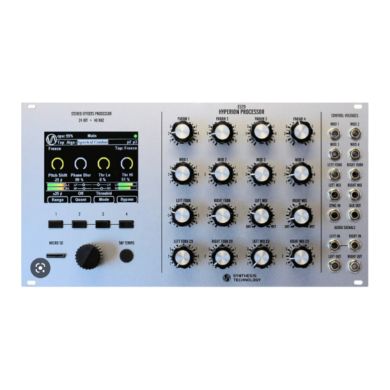
At power-up the Main Page is active. All effects are accessed in this page which is divided in five
separate areas:
1. Header area – contains the page title and several indicators, including the In/Out Filter status,
patch name, Mute status (speaker-slash icon) and EEPROM status light (green means
EEPROM is up-to-date, red means EEPROM will be updated with parameter changes within a
few seconds).
2. Menu area – contains four items which can be selected via the rotary encoder:
1. Exit – select this item and press the encoder button to leave the Main Page and enter the Top
Page which allows access to other menus that control the E520.
2. Algo – select this item and press the encoder button to select the active effect. Selection uses
a pop-up scrolling menu.
3. P2 – drops down into the algorithm-specific settings page where you can change parameter
routing options, In/Out filter settings and additional per-algo settings (if any).
4. P3 – drops down into the algorithm-specific patch page where you can load and save
patches for the currently selected algorithm.
3. Effect area – where the active algorithm renders its status
4. VU meters – L/R input and output volume indicators which show real-time signal levels on
input and output channels. When the VU meters show red then there is a strong likelihood of
clipping distortion.
5. Indicators for Feedback and Mix settings – four small slider widgets that show the current state
of the Feedback and Mix controls. When these controls are centered the 'thumb' of the widget is
a filled circle, otherwise it is an outline. When Feedback controls are centered the amount of
feedback is zero. When Mix controls are centered the output will be an equal proportion of wet
and dry signal.
6. Buttons – legends and status of the four UI buttons appear in this area. The three left-most
buttons are dedicated to effect parameters while the right-most button is always a bypass
function that disables the effect and passes audio thru the E520 without modification.
Pg2
Pg2 (Page Two) off the Main page provides a list of algorithm-specific settings including:
E520 Effects
V1.1 – Nov 15, 2020
Advertisement

Related Manuals for Synthesis Technology E520


Summary of Contents for Synthesis Technology E520
- Page 1 E520 without modification. Pg2 (Page Two) off the Main page provides a list of algorithm-specific settings including:...
- Page 2 These can be saved and loaded using either the four buttons, or the encoder. As shipped from the factory, at least one of these six will already be defined as a “factory preset”, created by our own Robert Rich to help demonstrate some of the unique capabilities of the E520. Top Page The Top page is used to select other functional pages.
- Page 3 8. Feedback Limiter – The feedback and filter resonance loops have an optional limiter to prevent runaway overloads (“explosions” or “screaming”). When the threshold loudness is exceeded the gain in the feedback loop is dialed down to prevent overload signals. There are four settings: 1.
-
Page 4: Patch Page
PAUSE mode. Allows loading the looper buffer with previously recorded material on the SD card. Note that while in the File page the E520 audio processing will be muted and the “Speaker-Slash” icon will be displayed in the upper right. -
Page 5: Color Page
About Overloads In a multi-effects processor like the E520 there are an infinite number of ways to generate overloads – situations where the output signal “blows up” and generates maximum loudness sounds that can potentially damage equipment and cause discomfort to the listener. To help avoid this, feedback limiting is included (see the description in the Preferences section) which defaults to providing some protection against this and supports even stronger levels of protection. - Page 6 75%. Emergency Mute If the E520 (or an upstream source) happens to generate undesired sounds, an “Emergency Mute” feature is provided that will quickly mute the output. Simply press any 3 of the LCD buttons simultaneously and output audio will cease and a small “Speaker-Slash” icon will appear in the upper...
- Page 7 3. InMix – The original E580 is a monophonic effect, so on the E520 which is stereo the two inputs are mixed according to this. Full CCW is 100% Left channel, full CW is 100% Right channel and 12:00 position is 50/50 mix.
- Page 8 2. BBD mode – reduces SNR by addition of noise. 3. Tape mode – controls random delay time variation. Similar to unstable tape speed warble. Buttons Three button functions are supported: 1. Range – Four delay settings for the fixed tap: 1x, 16x, 256x, 4096x allow delays from 0.196s to ~10min.
- Page 9 signifies that tempo is active and overrides the Range setting. Tap intervals longer than ~5 seconds cause the tempo calculation to reset. Auxiliary Output This effect has no auxiliary output. Clean Delay Overview The Clean Delay is a non-resampling delay (ie – the sampling rate is constant throughout the processing) which always runs at the full 48kHz rate and introduces no interpolation artifacts into the signal while the delay length is stable.
- Page 10 Feedback Feedback is active for this effect. Readouts There are five readouts for this effect: 1. Range – 1x thru 4096x 2. Swap – on/off 3. Filter – on/off 4. Time – main delay time in seconds 5. Offset – delay time of the tap in seconds Page 2 Settings There two additional Page 2 settings: ▪...
- Page 11 CV Inputs Four CV input parameters are supported: 1. Dly Len – this controls the length of the delay line. Varying this control in real-time will cause granular cross-fades as the length changes. The parameter readout is in percentage of the full range.
- Page 12 The parameter readout is in percent from 0-99%. Note – the E520 hardware does not support the full VCO range of the original Prime Time unit, so in the 1x Mult range the VCO Adj control doesn’t extend higher than 50%.
- Page 13 Buttons Three button functions are supported: 1. Delay Mult – Four delay multiplier ranges as in the original Prime Time: 1x, 2x, 4x, 8x. These settings reduce the effective sample rate by the selected amount. 2. Buf Len – three buffer length controls which enable delay settings beyond those of the original Prime Time.
- Page 14 resonant 4th-order lowpass filter is available in the feedback path if desired. The unique features are that this delay can be run forward or backwards and it can be “frozen” to keep playing the current delay contents without changing. CV Inputs Four CV input parameters are supported: 1.
- Page 15 4. Tempo Ratio – controls an additional ratio between the Tap Tempo and timing. Values are 1/1, 3/2, 2/1, 3/1, 4/1, 8/1, 16/1,2/3, 1/2, 1/3, 1/4, 1/8, 1/16 Feedback Feedback is active for this effect. Readouts There are four readouts for this effect: 1.
- Page 16 percentage with a maximum of more than 1 second. Current values of both parameters are displayed in a readout near the top of the screen. 2. Delay Time - this controls the delay over a 0-5ms range when in Time mode and a 20Hz-20kHz range when in Frequency mode, smoothly varying delay without granular artifacts but introducing considerable FM.
- Page 17 Auxiliary Output The delay time value (with offset and LFO) is available on the auxiliary output. Chowder Delay Overview The Chowder Delay is used to chop/slice incoming audio into “chunks” which are randomly reordered in time with optional reversing and pitch shifting. Various parameters provide control over the chunk size, probability of chopping, reversing and shifting, as well as the time span of reordering.
- Page 18 Right Feedback – Pitch Shift. Controls the amount of pitch shift applied to any stutter operation. CW from center is upward shifts while CCW from center is downward shift. Repeated stutters will compound shifts up to one octave and then wrap back to no shift. Readouts There are three readouts for this effect: 1.
- Page 19 Primary and Secondary, filtering and feedback all allow control over the complexity and dynamics of the output. Tap Tempo is used to set the base time rate and a selectable multiply/divide ratio can scale the rate. CV Inputs Four CV input parameters are supported: LPri Dnsty –...
-
Page 20: Auxiliary Output
Four CV input parameters are supported and their functions change with the selected pitch mode. Pitch sensitivity is approximately 1V/Oct – as close as is possible with the uncalibrated CV input paths on the E520 when the attenuator knobs are turned fully CW. Buttons... - Page 21 ◦ Off – no quantization. ◦ Chrom – chromatic 12-tone equally tempered scale ◦ Various major / minor / pentatonic scales ◦ Whole tone, Minor 3 , Major 3r, Octave scales Key : Selects the key of the scale Mode : Selects the pitch assignment mode ...
- Page 22 Auxiliary Output This effect does not drive the auxiliary output. Headspace Overview Headspace is a stereo image synthesizer which treats the Left and Right input signals as separate mono sources that can be placed in arbitrary positions about the listener’s location. It provides a toolkit of four different techniques: Swap –...
- Page 23 Three CV input parameters are supported: 1. InMix – The original E560 is a monophonic effect, so on the E520 which is stereo the two inputs are mixed according to this control. Full CCW is 100% Left channel, full CW is 100% Right channel and 12:00 position is 50/50 mix.
- Page 24 2. Ring Mod – Ring modulation. Input signal is multiplied by the carrier waveform which results in a more harmonically complex signal than Bode shifting. 3. Phase – Phase shifting. The internal carrier is disabled and instead the input signal is phase shifted by an amount ranging from 0-360deg as determined by the carrier control parameter.
-
Page 25: Frequency Shifter
Frequency Shifter Overview The Frequency Shifter is similar to the Deflector Shield but is a true stereo effect – the Left and Right channels are completely independent but can be processed with identical parameters. Similar frequency shifts, carrier morphing and modes are available but the output modes are limited to variations of Up and Down shifting. - Page 26 3. Out Mode – Up/Up, Up/Dn, Dn/Up, Dn/Dn 4. LFO BPM – the the Carrier frequency in Beats per Minute. Page 2 Settings One additional setting is available on Page 2 to enable or disable quantization of the carrier frequency in integer beats-per-minute.
- Page 27 1. Stages – Selects 1, 2, 4, 6, 8, 12, 18 or 24 stages of all-pass processing. Lower numbers of stages are gentle with 6 being similar to most analog phaser effects. 24 stages results in many more cycles of phase shift and produces a very resonant sound. 2.
- Page 28 1. Shift – this controls the amount of pitch shift. Parameter readout range is up to +/-2400 cents, depending on the Range selection. 2. Grain Size – this control varies the size of the cross-fade grains in the shift algorithm. Smaller grains result in a faster modulation rate and introduces a somewhat ring-mod sound.
- Page 29 Shimmer Reverb Overview The Shimmer Reverb is a reverberator combined with a granular pitch shifter in the feedback path that can be used to introduce a variety of ambient textures. It is a true stereo effect – the Left and Right channels are processed independently but share the same reverb loop so that sounds in one channel will reverberate in the other, but from a different part of the process so that stereo imaging does not collapse.
- Page 30 4. Tweak - - shifts down amount specified on Pg2. 5. 5 dn – shifts down a musical 5 . Orchestral. 6. Oct dn – shifts down an octave. Dark, imposing. 2. Shift R – selects one of 6 different shift amounts for the shimmer feedback in the Right channel. Uses the same selections as Shift L.
- Page 31 Offset Mode – a common delay offset for all phases is varied. This can be useful for adding tremolo by modulating the parameter in the 5-10Hz range with an external LFO (or an internal routable LFO). Tap phases are evenly spaced at intervals of 360/N where N is the number of phases selected by button 2. Phase Mode –...
- Page 32 Auxiliary Output The dedicated LFO signal for the Left channel is routed to the Auxiliary output. Voder Overview The Voder is a filter that shapes sound into vowels which are chosen from a set of 15 that were determined by research. It is a true stereo effect – the Left and Right channels are completely independent but can be processed with identical parameters.
- Page 33 4. Soft – Soft clipping on output of formant filter which sounds less harsh than hard clipping. 5. Dist – Variable distortion on output of formant filter with distortion order determined by Right FB control. Feedback Feedback is not enabled for this effect. Page 2 Settings No additional settings are available on Page 2.
- Page 34 3. HPF – Highpass Filter 1. Cutoff: Controls the cutoff frequency of the filter 2. Resonance: Controls the amount of resonance (peaking) at the cutoff frequency. 4. BPF – Bandpass Filter 1. Cutoff: Controls the center frequency of the filter 2.
- Page 35 2. LP cut – enables a lowpass shelf to keep diffusion from oscillation when feedback is applied. 12. Shimmer 1. RT – reverberation time. Varies 0.1 – 10s 2. Shift – amount of pitch shift applied in feedback loop. Varies +/-2400 cents. 3.
- Page 36 Readouts There no additional readouts for this effect. Tap Tempo Tap Tempo is active and and controls delay range for the RsDly sub-algo. A Page 2 setting can disable tap control for each channel. Auxiliary Output There is no Auxiliary output for this algorithm. Looping Effects Looper Overview...
- Page 37 4. Pause – this temporarily halts the record and/or play process. Pressing again will resume record/play at the same point in the memory. While in Pause mode you can load and save the contents of the loop to the SD card. Feedback Feedback controls the amount of original signal from the loop is mixed back in during overdub.
- Page 38 Spectral effects are processed in the frequency domain using the Fast Fourier Transform. All spectral effects in the E520 use a 1024 point complex FFT to provide two 512 point real transforms at a rate of 2.7ms which provides a good compromise between time and frequency resolution, while allowing full stereo processing for most effects.
- Page 39 2. Threshold – filters out all bins with loudness that don’t fall between the Low and High threshold settings. CV #3 is the low threshold – all bins quieter than this will be dropped. CV #4 is the high threshold – all bins louder than this will be dropped. 3.
- Page 40 Spectral Time Machine Overview The Spectral Time Machine is a combination of a looper, pitch shifter and time stretcher. A large (5.8 minute) memory records and loops sounds which can be played back continuously or looped with variable speed and pitch. Due to the processing overhead this is a mono effect – Left and Right channels are mixed 50/50 prior to input.
- Page 41 4. Pause – recording is stopped. Press Tap to return to Overdub mode. In this mode you can use the File page to load and save the contents of the looping memory to SD card. 2. Quant – Enables Equal Tempered quantization (100 cent) of the Pitch Shift parameter. 3.
- Page 42 CV Inputs Four CV input parameters are supported: 1. Delay L – This controls the amount of delay applied to the Left channel. The range is 0 to 1.96 seconds. 2. Pitch L – This controls frequency-domain pitch shift by up to +/- 2 octaves for the Left channel. The parameter reads out in cents over the full range of +/-2400 cents.
- Page 43 Spectral Delay Overview The Spectral Delay is a stereo effect which delays each spectral bin by different amounts. Several modes are provided to vary the bin delays in different ways. Left and Right channels have independently controlled delay parameters. CV Inputs Four CV input parameters are supported but their function varies depending on the operating mode so see below for details: 1.
- Page 44 1. Left Pitch – introduces a slight pitch shift into the left channel for slippery sounding feedback. 2. Right Pitch – introduces a slight pitch shift into the right channel for slippery sounding feedback. 3. Phase Blur – enables phase blurring on both channels. Readouts There are five readouts for this effect: 1.
- Page 45 2. Tilt – this parameter provides a coarse equalization and ranges from 0.99 to -0.99. Fully CCW (0.99) the low frequency response is emphasized and at fully CW (-0.99) the high frequency response is emphasized. In the center the overall response is flat with frequency. 1.
- Page 46 CV Inputs Four CV input parameters are supported but their function varies depending on the operating mode so see below for details: 1. Length – This varies from 0.01 second to 10 seconds and controls the nominal length of the sampling interval.
- Page 47 Readouts There are two readouts for this effect: Left and Right Ping mode status is shown above the parameter widgets. Page 2 Settings There is one Page 2 setting which enables quantization of the pitch shifts to 100cent intervals. Tap Tempo Tap Tempo is active and can perform one of two functions: Sync Interp - synchronizes the sampling interval.
- Page 48 4. Resonance – this controls the resonance peak of the audio lowpass filter. Use it to enhance the formant of the ‘wah-wah’ effect to make the baby cry harder. Buttons Three button functions are supported: 1. Detector – selects one of five different detection algorithms: I.
- Page 49 CV Inputs Four CV input parameters are supported: Bits – does bit crushing from 24 bits down to just 1. Optional dither noise may be added with button 1. Sample – does sample rate reduction from 48kHz down to 48Hz to introduce aliasing. Two ...
- Page 50 Tap Tempo Tap Tempo is a “Drag” effect which is akin to touching the edge of a tape reel. While the Drag effect is applied the sound will pitch down momentarily and speed up when the effect is released. Auxiliary Output The is effect has no Auxillary output.
- Page 51 14Vpp input range for a sine waveform. The 0dB tic is the nominal 10Vpp level of a Synthesis Technology oscillator. Note that like a normal analog VU meter, this level meter is sensitive to wave shape, so a 10Vpp square wave will peg the meter even though it doesn’t actually saturate the codec input.
-
Page 52: Revision History
Tap Tempo Tap Tempo is used for external triggering. Auxiliary Output This effect has no auxiliary output. Revision History V0.1 – Oct 10, 2019: Initial release V0.2 – Nov 4, 2019: Updates for new functionality. Added Main Page P2, P3, Clean Delay Tap offset, Scope mode. - Page 53 Sync div rate prefs selection & logic for algos w/o divs Buffer load for looper and spectral time Time Machine factor quantization on Pg2 Flanger sweeps 20Hz-20kHz in freq mode Tap ratios in clean, mini, resamp, reverse algos Vref & die temp readouts to About pg. Freeze option on pg2 for Spectral Drones Bugfixes: Fix freeze mode click in minidelay...
Need help?
Do you have a question about the E520 and is the answer not in the manual?
Questions and answers