Advertisement
Quick Links
PAGE 1
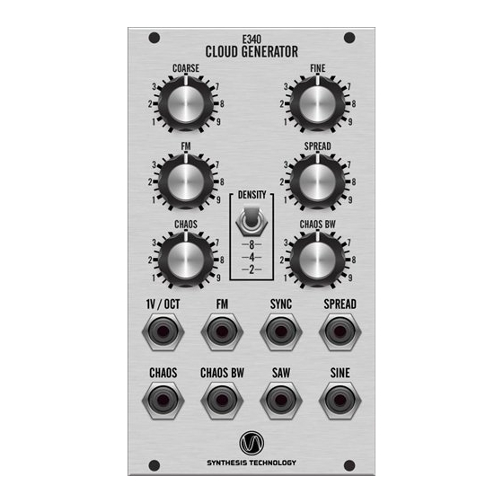
E340 Cloud Generator DIY Kit
www.synthtech.com/euro/e340
What is the E340?
The Synthesis Technology E340 is a dual output VCO that contains 8 oscillators. These
oscillators can be detuned by a control voltage (SPREAD) and internally modulated by
filtered noise (CHAOS and CHAOS BW). A SYNC input resets all oscillators when the
SYNC signal is above 0.25V (also called 'hard sync').
Connecting to the power supply
The E340 can use either a MOTM 4-pin, MTA-156 style connector (+-15V) or a 16-pin
Euro style (+-12V) connector. See the photos below. The Euro ribbon cable has a red
stripe to indicate -12V. The supplied Euro power cable is keyed so that when inserted
in the E340, the red stripe is 'down' (towards the jacks) and by the white lettering on
the pc board.
Advertisement

Related Manuals for Synthesis Technology E340


Summary of Contents for Synthesis Technology E340
- Page 1 Euro style (+-12V) connector. See the photos below. The Euro ribbon cable has a red stripe to indicate -12V. The supplied Euro power cable is keyed so that when inserted in the E340, the red stripe is ‘down’ (towards the jacks) and by the white lettering on the pc board.
- Page 2 4- This is where the Euro power cable goes (see Page 1) 5- This is the DSP programming header. DO NOT CONNECT ANYTHING TO HERE! 6- Option jumpers, these are NOT USED on the E340 so leave them alone. 7- 1V/OCT trimmer. This trimmer is NOT ADJUSTED at the factory! 8- This switch is NOT PRESENT on the E340.
- Page 3 PAGE 3 grounded. If non-shorting jacks are used (like banana) then you may experience small variances in output frequency. Here is how to connect to the pot & jack board Step 1 Decide if you want to keep the toggle switch soldered to the front panel (highly recommended) or not.
- Page 4 PAGE 4 Step 3 Wire up the 8 jacks. Refer to the photo below: You will notice that PIN 1 of the jack connectors has a square pad. As before, insert the wire from this side and solder on the back side. The connections to the jacks are as follows: 1 –...
- Page 5 PAGE 5 Step 4 Attach the DSP board to the front board. You will note there are 3 gold-plated headers that are on the rear of the pot/jack board. These will solder to the top (component) side of the DSP board. See the photo below: NOT PRESENT >>>...
- Page 6 PAGE 6 Step 5 There are 3 jumper options on the DSP board as follows: JP4 – buss CV. This is for Doepfer-style bussboards. The default position is OUT (the buss CV is not connected to the 1V/OCT summer). Placing the jumper to the IN position will cause the buss CV to be added to the overall frequency summer.
Need help?
Do you have a question about the E340 and is the answer not in the manual?
Questions and answers