Table of Contents
Advertisement
Quick Links
PAGE 1
E580 Resampling Mini-Delay DIY Kit
www.synthtech.com/euro/e580
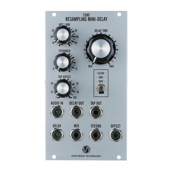
What is the E580?
The Synthesis Technology E580 is a mono-in, mono-out audio digital delay that uses a unique
'resampling' algorithm to mimic analog BBD and tape delays. Analog delays have the property
that when the delay time is changed, the pitch of the output changes. The E580 recreates this
effect. There are 3 modes: clean, BBD and Tape. The BBD mode adds a low-pass filter that is
based on delay time as well as noise. The Tape mode adds non-linear distortion (tape
saturation effect) and "wow & flutter" (motor speed variations). The E580 has 2 outputs: a
main Delay and a Tap. The Tap is a percentage (0-100%) of the main Delay. All 4 panel
controls are also under CV (-5V to +5V range).
Connecting to the power supply
The E580 can use either a MOTM 4-pin, MTA-156 style connector (+-15V) or a 16-pin Euro
style (+-12V) connector. See the photos below. The Euro ribbon cable has a red stripe to
indicate -12V. The supplied Euro power cable is keyed so that when inserted in the E580, the
red stripe is 'down' (towards the jacks) and by the white lettering on the pc board.
Advertisement
Table of Contents

Related Manuals for Synthesis Technology E580


Summary of Contents for Synthesis Technology E580
- Page 1 ‘resampling’ algorithm to mimic analog BBD and tape delays. Analog delays have the property that when the delay time is changed, the pitch of the output changes. The E580 recreates this effect. There are 3 modes: clean, BBD and Tape. The BBD mode adds a low-pass filter that is based on delay time as well as noise.
- Page 2 PAGE 2 What’s in the Kit (Power Cable Included, not Shown) What you will need to supply 4ea 50K or 100K linear pots (either one will work fine) and 7 jacks. These can be banana, 3.5mm or 1/4”. The MODE switch is pre-soldered, but you can remove/replace it if you are careful.
- Page 3 PAGE 3 The switch has 2 mounting nuts. For maximum mounting strength, the ‘bottom nut’ should be threaded up touching the rear of the front panel before the ‘top nut’ is tightened. Also note that when the toggle switch it flipped ‘up’ (say to select the CLEAN mode) this means the center pin (COMMON) is connected to the bottom switch lug.
- Page 4 PAGE 4 Step 3 Wire up the 7 jacks. Refer to the photo below: Notice that PIN 1 of the jack connectors has a square pad. As before, insert the wire from the ‘front’ side and solder on the back side. The connections to the jacks are as follows: TOP ROW BOTTOM ROW...
- Page 5 PAGE 5 General Info CV Inputs: -5V to +5V, DC to 8KHz. Audio Input: -5V to +5V maximum, 18KHz bandwidth (clean mode). Important Note: in order to have maximum Feedback settings without clipping, the maximum audio input level is 5V pk-pk (~+4dBm or ‘line level’). Audio input levels greater than 5V pk-pk will reduce the overall Feedback range until clipping occurs.
Need help?
Do you have a question about the E580 and is the answer not in the manual?
Questions and answers