Table of Contents
Advertisement
Quick Links
Advertisement
Table of Contents

Related Manuals for Array electronic FAB2 Series


Summary of Contents for Array electronic FAB2 Series
- Page 2 Preface Preface Thank you for choosing the FAB2 series intelligent controller. We recommend that you take some time to read this manual before using FAB2 products. You will find many more advantageous properties of FAB2, which will greatly simplify your operations of the FAB2.
- Page 3 FAB2 Intelligent Controller IMPORTANT APPLICATION NOTES: 1. The AF-C232/D232, AF-C485/D485, and LCD board, when a FAB2 is powered, must not be plugged in or out. 2. The default password for FAB2 is 0001. 3. The default address for FAB2 is 000. 4.
- Page 4 Contents Caution It indicates that if appropriate precautions are not taken, incidents of personal injury, damage or some loss of property will be caused. Note It indicates that particular attention is required to all published information related to the use or disposal of products. Qualification Only suitably qualified personnels are allowed to operate and debug the products.Qualified personnels are specified as those persons who carry out...
-
Page 5: Table Of Contents
FAB2 Intelligent Controller Contents Chapter I Introduction 1.1 Structure of FAB2 .................11 1.2 Parameters and models ..............12 1.3 FAB2 Features ................13 Chapter II Installation and wiring 2.1 Installation ..................15 2.1.1 Methods ...................15 2.1.2 Dimensions (unit:mm) ............15 2.2 Wiring of FAB2 ................16 2.2.1 Connection of power supply ..........16 2.2.2 FAB2 input connection ............17 2.2.3 FAB2 output connection ............18... - Page 6 Contents 3.2.5 RS .....................35 3.2.6 CPG (clock pulse generator) ..........36 3.2.7 RPR ..................37 3.2.8 UCN ..................38 3.2.9 DCN ..................39 3.2.10 MPLR (Single-pulse time relay) .........40 3.2.11 AN ...................41 Chapter IV Programming on FAB2 panel 4.1 FAB2 status display interface ............ 43 4.2 Password confirming ..............44 4.3 Function Interface ................44 4.3.1 FAB2/Rom Interface ..............45...
- Page 7 FAB2 Intelligent Controller ChapterVI Applications 6.1 Bell control for schools and factories ........57 6.2 The multi-function switch for lights in stairs and halls ..59 6.3 Auto-gate control .................59 6.4 Ventilation system ...............60 6.5 The neon lamp control system ...........61 6.6 Illumination system for display windows .........63 6.7 Application of FAB2 in building management ......64 6.8 Application of FAB2 in a voltage diode counting and packing assembly line ................65...
- Page 8 Contents 3.1.3 Communication ..............79 3.1.4 Display ..................79 3.1.5 Options ..................80 3.1.6 Help ..................80 3.1.7 Edit ...................81 3.1.8 Search ..................81 3.1.9 FAB2 Operation ..............82 3.1.10 Windows ................82 3.2 Tool Bar ..................83 3.2.1 Standard Tool Bar ..............83 3.2.2 Control Tool Bar ..............83 3.3 Block Library ................84 3.3.1 Block Library Operation ............86 3.3.2 Block classification ...............86...
- Page 9 FAB2 Intelligent Controller 4.2.5 Delete block or link ............102 4.2.6 Simulation operation ............103 4.2.7 Save and Print ..............104 4.2.8 Write/Read ................105 SP-AS/AL Series Switch Power 1.1 Introduction and Installtion Dimensions .......108 1.2 Features ..................109 1.3 Using Methods ( Taking SP-24AL as example) ....110 1.4 Specification ................113 (I) Functional comparison ............114 (II) Technical Parameters...
- Page 10 Contents This manual contains the precautions necessary for ensure your personal safety as well as for protection of the products and the connected equipment. These precautions are highlighted with Safety Guide a triangle WARNING symbol in this manual and are marked according to the danger levels as following: Danger It indicates that if appropriate precautions are not taken, serious...
- Page 11 FAB2 Intelligent Controller MEMO...
-
Page 12: Chapter I Introduction
LCD panel, which greatly reduces the user’s cost investment, and for the operation It brings great convenience.The volume of FAB2 series products follows the old FAB’s small size, light weight and other characteristics, and is especially suitable for internal installation and use.Now FAB2 are being widely used in many fields such as industry,commerce,mining, agriculture, home automation etc. -
Page 13: Parameters And Models
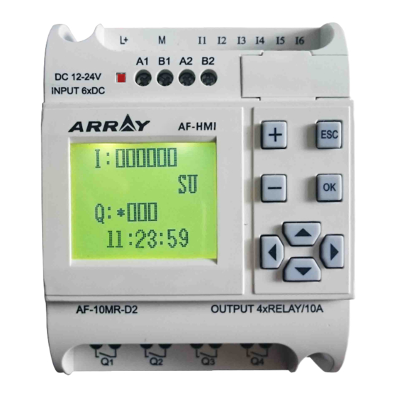
FAB2 Intelligent Controller 1.2 Specifications and models Item Type Power Input Output 6 points AC digital AF-10MR-A2 AC100V-240V 4 points relay output input AC14-20V/ 6 points AC/DC AF-10MR-E2 4 points relay output DC12-24V digital input 6 points DC digital 4 points transistor output AF-10MT-E2 DC12-24V input... -
Page 14: Fab2 Features
Chapter I Introduction 1.3 FAB2 Features 1. Removable LCD display (AF-HMI) AF-HMI(Removable LCD display) can be used flexibly according to your needs. When you need it, you can install and use the keys on the panel to query/ set the FAB2 address, FAB2 system time, modify the function block parameters and manually calibrate the analog quantity, etc. - Page 15 FAB2 Intelligent Controller 5. Real-time clock function The FAB2 has a clock-recording function that can run at any time you need, and you can set up to 127 different time periods, especially for systems that require time control.The timing is accurate to the second, and FAB2’s RTC precision error is greatly improved to 20s/month compared with FAB, making your time control more accurate.
-
Page 16: Chapter Ii Installation And Wiring
Chapter II Installation and wiring Chapter II Installation and wiring 2.1 Installation 2.1.1 Methods FAB2 is small so it is suitable to be fit inside panels or machinery. The installation of FAB2 is extremely easy. 1.Use standard 35mm DIN rail mounting FAB2, as shown in Fig 2.1, 2.Use the screw mounting holes on FAB2 for direct mounting Screw mounting hole 35mm DIN rail... -
Page 17: Wiring Of Fab2
FAB2 Intelligent Controller Fig. 2.3 AF2-20 Series (mm) 2.2 Wiring of FAB2 Screwdriver with a spade tip width of 3mm is needed for the wiring of FAB2 series. As for the cross section of a wire. The following two sizes are at choice: ※... -
Page 18: Fab2 Input Connection
Chapter II Installation and wiring FAB2 series power wiring diagram is as shown in Fig 2.4 and Fig 2.5, Fig 2.4 AC type Fig 2.5 DC Type 2.2.2 FAB2 Input Connection FAB2 input can be either switch,such as on/off switches and photoelectric baffle and sunshine switch etc.,or analog, such as pressure, temperature, humidity, flow... -
Page 19: Fab2 Output Connection
FAB2 Intelligent Controller FAB2 input connection is shown as shown in Fig 2.6 and Fig 2.7 and Fig 2.8, AC0-240V DC0-240V AC100-240V DC100-240V Fig 2.6 AC Type Fig 2.7 DC Type DC0V-10V DC12V-24V +DC10V Fig 2.8 DC Type (D/GD) 2.2.3 FAB2 output connection AF-10MR-A2/AF-20MR-A2/AF-10MR-E2/AF-20MR-E2/AF-10MR-D2/AF- 20M R-D2 type FAB2 is the relay output, the relay’s contact to the power and input is isolated. - Page 20 Chapter II Installation and wiring The connection is shown as shown in Fig 2.9, AC/DC power supply Fig 2.9 Relay output 2.Requirements for the transistors outputs The transistor is divided into D type and GD type The load connected to FAB2 must have the following characteristics: When the switch is ON(Q=1), the maximum current is 2A.
- Page 21 FAB2 Intelligent Controller 2)Type GD connection is shown in Fig2.11, FAB2 L power supply Fig 2.11 Transistor Output(GD type) 1."L+" line should be connected to "L+" of FAB2 power supply, and the load should be directly connected the "M" of the load power.
-
Page 22: Chapter Iii General Descriptions For Function Blocks
Chapter III General Description of Function Blocks Chapter III General Description of Function Blocks FAB2 series adopts the programming method with the use of function blocks. 17 function blocks are configured in total, and each block can achieve a specific control function independently, e.g. time-delay ON, time-delay OFF, setting switch time, counter function, etc. -
Page 23: And
FAB2 Intelligent Controller = 1 Dual commutator contact & Parallel connection of NAND NC contacts Serial connection of ≥ 1 NC contacts 3.1.1 AND The electrical line diagram for serial The symbol of AND is shown in connection of a certain number of NO the follows: contacts is shown as follows: &... -
Page 24: Not
Chapter III General Description of Function Blocks 3.1.2 OR The electrical line diagram for the parallel The symbol of OR is shown connection of a certain number of NO in the follows: contacts is shown as follows: ≥ 1 This function block is called as OR, because the status for at least one of inputs I1 or I2 or I3 is 1 (i.e. -
Page 25: Nand
FAB2 Intelligent Controller Logical frame of NOT: 3.1.4 NAND The electrical line diagram for parallel The symbol of NAND in FAB2 is connection of certain number of NC shown as follows: contacts is shown as follows & This function block is called NAND, because only when all I1, I2 and I3 are in status 1 (i.e. -
Page 26: Nor
Chapter III General Description of Function Blocks 3.1.5 NOR The electrical line diagram for parallel The symbol of NOR in FAB2 is connection of a certain number of NC shown as follows: contacts is shown as follows: ≥ 1 Only when all the input of NOR function blocks are at a low potential (status 0), the output will be closed (status 1). -
Page 27: Special Function Blocks (Sf)
FAB2 Intelligent Controller When the status of input are not the same, the output status of XOR is 1. When the status of input are the same, the output status of XOR is 0. Logical frame of XOR: 3.2 Special function blocks (SF) Function Representation Graphic... -
Page 28: Dpr
Chapter III General Description of Function Blocks RPR (Hold ON time-delay relay) UCN (Up-counter) DCN (Down- counter) MPLR (Single pulse time relay) MPLR AN (analog input block) 3.2.1 DPR Line diagram/Symbol in FAB2 Description After TRG is triggered, the time delay timer starts timing. -
Page 29: Ddr
FAB2 Intelligent Controller Time Sequence Frame: Description: 1. When the status of TRG input changes from 0 to 1, the time-delay timer starts timing. If Input TRG holds status 1 for a sufficiently long time, the output will be changed to 1 after the time T is over. There is a time delay between the input turning ON and the output turning ON, which is why the ON time-delay is so called. -
Page 30: Plr
Chapter III General Description of Function Blocks Time Sequence Frame: Description : 1. When Input TRG is at Status 1, Output Q changes at once to Status 1. When Input TRG changes from 1 to 0 (i.e. the descending edge comes), the internal time delay timer of FAB2 is activated and the Output Q still remains at Status 1. - Page 31 FAB2 Intelligent Controller Time Sequence Frame: Descriptions: 1. Every time the trigger input TRG changes from status 0 to Status 1, the status of Output Q will change accordingly (The status of Q will be reversed). 2. Reset Q to Status 0 via Input R. 3.
- Page 32 Chapter III General Description of Function Blocks Notes regarding the time “CW”: 1. When the date system is selected for the timing of a time switch A. For the same output channel, up to 127 time switches can be set, and these switches must be put in order according to the time sequence, e.g.
- Page 33 FAB2 Intelligent Controller Secondly: you should select TU, and set it as follows. 24:00 8:00 This setting means no ON time 24:00 Then, it can let Q1 switch on at 6:00 on Monday and switch off at 8:00 on Tuesday. Note: You can directly set time as follows by using Quick II, the programming Software.
- Page 34 Chapter III General Description of Function Blocks The following definition should be noted. For example, ON: 5:00 every Sunday OFF: 8:00 every Monday It can be programmed by three blocks as follows: 8:00 24:00 24:00 5:00 Notes: MO: Monday MO-SU: every day from Monday to Sunday TU: Tuesday MO-TH: every day from Monday to Thursday WE: Wednesday...
- Page 35 FAB2 Intelligent Controller May 1st, 2018 9:00 11:00 Q1 (OK) 12:00 17:00 May 1st, 2018 9:00 11:00 Q1 (ERROR) 8:00 8:30 9:00 11:00 Q1 (OK) 15:00 18:00 9:00 11:00 Q1 (ERROR) 6:30 8:30 Note: This phenomenon follows the principle that latter commands surpass former ones.
- Page 36 Chapter III General Description of Function Blocks 8. Clock hold circuit For a FAB2, when there is a power failure, the internal clock will continue running. The time that the FAB2 can maintain the internal clock to run depends on the temperature. When the temperature of the FAB2 is 25 ℃ , the clock is able to continue its normal operation for more than 160 hours after the power is cut off.
-
Page 37: Cpg (Clock Pulse Generator)
FAB2 Intelligent Controller Switch characteristics RS relay is a simple trigger. The output value depends on the input status and the original output status. The following list of true values is used to describe the logic relations: REMARK Status remains the original value Reset Reset (taking priority over Set) 3.2.6 CPG (clock pulse generator) -
Page 38: Rpr
Chapter III General Description of Function Blocks Time sequence frame is as follows: Notes: 1. Use Parameter T to set ON/OFF time. The assignment range of T is 0.01 ~ 99.99, and the time units can be set respectively to hour (H), minute (M) and second (S). -
Page 39: Ucn
FAB2 Intelligent Controller Time Sequence Frame: Notes: 1. If the status of Input TRG changes from 0 to 1, the internal timer will be activated. When time T is over, Output Q becomes 1 and then the returned input TRG has no effect on output Q .Only when Input R becomes 1 again Output Q and Timer T will be reset to 0. -
Page 40: Dcn
Chapter III General Description of Function Blocks Time Sequence Frame(PAR=5): Note: This function is applicable to the cases that counting is required. 3.2.9 DCN Line diagram/Symbol Description in FAB2 R takes priority over other inputs. When R Input R inputs a reset signal, the counter is reset to 0 and output Q resets simultaneously. -
Page 41: Mplr (Single-Pulse Time Relay)
FAB2 Intelligent Controller 3.2.10 MPLR (Single-pulse time relay) Line diagram/Symbol Description in FAB2 Trigger an input to activate the single-pulse Input TRG time relay. When the leading edge of TRG comes, a pulse with the duration of T is output. Reset the single-pulse time relay. - Page 42 Chapter III General Description of Function Blocks 3.2.11 AN Figure in FAB2 Description Comparative input port 1, with Input 1 0.0~10.0, I1~IC to be selected. Input 2 Function selection >,<,≥,≤. 输入 1 输出 Q 输入 2 Comparative input port 2, with Input 3 输入...
- Page 43 FAB2 Intelligent Controller MEMO...
-
Page 44: Chapter Iv Programming On Fab2 Panel
Chapter IV Programming on FAB2 panel Chapter IV Programming on FAB2 panel FAB2 operation panel is a simple man-machine interface, which is completed by the following eight buttons to complete the panel operation. Fig 4.1 4.1 FAB2 status display interface After the FAB2 is powered on, the AF-HMI enters the FAB2 status display interface. -
Page 45: Password Confirming
FAB2 Intelligent Controller 4.2 Password confirming When the user observes the AF-HMI in the above status display interface, press the “ESC” and “OK” keys at the same time to enter the password confirmation screen, as shown in Fig 4.3, FAB2 needs to enter the password value at this time, and the cursor stays at the high position of the password.You can use the +/- keys to change the numeric value (0-9). -
Page 46: Fab2/Rom Interface
Chapter IV Programming on FAB2 panel > Editor.. FAB2/Rom Set.. Fig 4.4 Function Interface 4.3.1 FAB2/Rom Interface When the user enter into the FAB2/Rom interface as shown in Fig 4.5, then when the user enters the Calibrate interface, Rom → FAB2 interface and FAB2_ Addr interface under the FAB2 function interface, the FAB2 machine will stop running. - Page 47 FAB2 Intelligent Controller C A L I B A I: 0 0 Va l ue : 00 00 Fig 4.6 2. When the minimum value is prompted, an external power supply is required to input the minimum voltage value for this channel, then press OK to confirm and mark as Vmin.
-
Page 48: Rom→Fab2 Program Interface
Chapter IV Programming on FAB2 panel 4.3.1.2 Rom→FAB2 Read/write/modify Program Interface The user can view the function block number of the FAB2 program on this interface, and can modify the parameters of the function block number.Such as DPR,DDR and UCN and so on. When the user enters the Rom →... - Page 49 FAB2 Intelligent Controller B018 COUNTU PreC Counter 000100 Fig 4.9 3) Clock switching function The parameter setting of the clock switch function block is divided into date type and week type. For example, as shown in Fig 4.10 B000 function block for SCHD clock switch week type, open Monday to Saturday 8:30.
-
Page 50: Fab2_Addr Address Interface
Chapter IV Programming on FAB2 panel 4.3.1.3 FAB2_Addr address interface The User can view the address of FAB2 machine in Fig 4.12, and can modify his address. When the user enters the FAB2_Address interface through the FAB2/Rom interface, the FAB2 address can be viewed or modified through the +/- keys. FAB2_Addr Fig 4.12 4.3.2 Setting interface... -
Page 51: Edit A Fab2 Function Program
FAB2 Intelligent Controller 4.4 Edit FAB2 function program During editing of FAB2 function program, special attention need be paid to Some programming rules, the application of the mid-relays and how to use FAB2’s operation key panel with LCD to edit the FAB2 function program. 4.4.1 Programming rules Rule 1: Before entering the line, you need to draw a complete circuit diagram on the drawing and indicate the intermedicate relay (M) you need to use, ordirectly... -
Page 52: Intermediate Relay
Chapter IV Programming on FAB2 panel Rule 4: One output may be connected to multiple inputs, but multiple outputs cannot be connected to one input. Rule 5: At power-on and initialization of FAB2 (at the instant of power-on), the intermediate relay (M) and output port (Q) are all in logical 0 status. Their later status will be determined by the program. - Page 53 FAB2 Intelligent Controller Fig 4.15 In the above figure, the output status of B01 can be registered by M01 in addition to iuput of the B02 module, and then used as the input of the B03 module. MEMO...
-
Page 54: Chapter V Communication Connection
Chapter V Communication connection Chapter V Communication connection FAB2 series PLC not only has a download port custom protocol, but also supports Modbus RTU protocol, and can communicate with other devices that support modbus RTU protocol. The upper right side of the FAB2 is the program download port, as shown Fig 5.1 The upper left side of FAB2 front view is 485 interface, as shown in Fig 5.1... -
Page 55: Fab2 A2B2 Interface
FAB2 Intelligent Controller Address Read-write Function Comment Type Property Code Only Read Read the status of system (00-FF) Only Read Read status of digit input(100-1FF) Only Read Read status of AI(300-3FF) Only Read Read status of Output Q(200-2FF) 1:FAB2 is act as Modbus slave device, which responds according to the requested data by Modbus master device. - Page 56 Chapter V Communication connection Write empty output port Function status (unoccupied output Write keys port in FAB2 program) Reading input analog 1-12 Read value (DC PLC) Dynamic Corresponding Reading parameter values text block number in FAB2 Read of function blocks in FAB2 program (1-128) programs Reading input analog...
- Page 57 FAB2 Intelligent Controller MEMO...
-
Page 58: Bell Control For Schools And Factories
Chapter VI Application Chapter VI Application FAB2 has a very wide application range. In order to let the user know the wide application area and the convenience for FAB2, we will show some common and representative control schemes herein. After you read these schemes, it is easy and convenient for using FAB2 to achieve automatically control requirements, especially in a system requiring time control and intelligent living area etc. - Page 59 FAB2 Intelligent Controller When FAB2 is used for the above control, it is very simple both in the connection of the external line and in editing the program. When QUICK II programming software is used for editing the control program, it is only necessary to set two time switch blocks.
-
Page 60: The Multi-Function Switch For Lights In Stairs And Halls
Chapter VI Application 6.2 The illumination of multi-function switch in stairs and halls Control requirements: 1. When pressing switch, illumination is turned on, and automatically turned off after 3 minutes. Illumination is twinkled 5 seconds before automatically turned off. 2. Illumination is always turned on after pressing twice in 5 seconds. 3. -
Page 61: Ventilation System
FAB2 Intelligent Controller The Function Block Program Diagram is as follows: Description: I1, connected to the open switch I2, connected to the stop switch I3, connected to the safe pressure damper I4, connected to the close switch Q1, connected to the flashing lamp Q2, connected to the gate-open motor contactor Q3, connected to the gate-close motor contactor 6.4 Ventilation system... -
Page 62: The Neon Lamp Control System
Chapter VI Application 5. In case of any fault in the ventilation system, the alarm lamp shall be on. The ventilation system is controlled by the flow sensor; if no atmosphere flows in the room, then wait a short time, cut off this system and send failure. The Function Block Program Diagram is as follows: Description: I1: connected to the start button... - Page 63 FAB2 Intelligent Controller It can be activated by the manual switch at any time; when the clock switch or light sensitive switch triggers, it can be activated. (3) The light sensitive switch shall be provided to complement the time switch, so that the lamp will be automatically turned on when the light is weak and off when the light is sufficient.
-
Page 64: Illumination System For Display Windows
Chapter VI Application 6.6 Illumination system for display windows Control requirements: 1. The display time Monday to Friday 8:00~22:00 Saturday 8:00~23:59:59 Sunday 9:00~20:00 2 . Requirement in display time a. The basic lighting Open the basic lighting equipment; Close the additional lighting and the lighting for non-display period; b. -
Page 65: Application Of Fab2 In Building Management
FAB2 Intelligent Controller Description: I1: connected to the detect test switch I2: connected to the light sensitive switch Q1: connected to the non-display lighting Q2: connected to the additional lighting in display time Q3: connected to the basic lighting in display time 6.7 Application of FAB2 in building management Control requirements: 1. -
Page 66: Application Of Fab2 In A Voltage Diode Counting And Packing
Chapter VI Application 2) Assignment of FAB2 I/O points Input part: I1- connected to the temperature sensor I2- connected to the smoke detector I3- connected to the door/window sensor I4- connected to the gas detecting sensor I5- connected to the water meter I6- connected to the gas meter I7- connected to the watt-hour meter Output part: Q1- connected to the air-condition equipment... - Page 67 FAB2 Intelligent Controller ( 三 ) Monitoring of all FAB2s can be realized by installation of monitoring software on PC. Each FAB2 answers the instruction of PC through bus 485, including diode counting and I/O status for FAB2; the data from FAB2 is displayed on PC screen and saved on PC, as well PC can acquired FAB2 data on the screen and can provide data storage and inquiry functions, to allow prompt analysis of the counting of different withstand voltage diodes.
- Page 68 FAB2 Intelligent Controller QuickII: SOFTWARE FOR FAB2 Controller QUICK II is programming software for FAB2 to perform programming and simulation on PC. It can not only perform edit of control program (FBD) for FAB2, but also simulate program and display clearly the running results in order to determine the accuracy.
-
Page 69: Chapter I Installation And Unloading
Chapter II Installation and uninstallation Chapter I Installation and unloading 1.1 Installation of Quick II The installation of Quick II is very simple. A prompt dialogue box will appear automatically and you will complete the installation smoothly on your PC . The main steps are as follows: 1. - Page 70 FAB2 Intelligent Controller - If you click NEXT to enter the next step of installation, the User Name and Computer Name will be displayed, as shown in Fig. 1.3, and you can modify them. - If you click CANCEL, the installation program will be terminated. Fig 1.3 3.
- Page 71 Chapter II Installation and uninstallation 4. Enter the next frame of “ Ready to install the program”, as shown in Fig1.5 - Click the (Back) button with the left mouse button, you will return to the previous installation screen, as shown in Figure 1.4. - Click the (Install) button with the left mouse button, you will enter the installation interface, as shown in Figure 1.6.
-
Page 72: Unloading
FAB2 Intelligent Controller 6. Enter into the “Installshiled Wizard Complete” screen as shown in Figure 1.7 and click “Finish” with the left mouse button to end the entire installation process. Fig 1.7 7. Enter installing step automatically, if quit setup, click “cancel” button. Fig 1.8 1.2 unloading There are two ways to unload QUICK II:... - Page 73 Chapter II Installation and uninstallation - A confirmation uninstall dialog appears, click “Yes” - The removal screen appears as shown in Figure 1.10, which can be removed. Fig 1.9 unloading This removal method is quite convenient for the user. 2. Remove on the desktop - Under the Windows screen, double-click “My Computer”...
- Page 74 FAB2 Intelligent Controller Fig 1.11 The semoval screen of Quick II MEMO...
-
Page 75: Chapter Ii Brief Introduction To Quick Ii
Chapter II Introduction to Quick II Chapter II Brief Introduction to Quick II In order to obtain a quick and initial understanding of Quick II, we will, from this chapter forward, make a comprehensive introduction to Quick II with the help of visual pictures. -
Page 76: Editing Windows Of Logical Diagram For Fab2
FAB2 Intelligent Controller Fig 2.2 For QUICK II, we can use pull-down instruction tools and shortcut button to operate, and all function blocks are directly distributed in the window. Operating in the window with the mouse you can finish creation and writing, simulation, running and monitoring of a FAB2 program very quickly. -
Page 77: Main Functions
Chapter II Introduction to Quick II 2 .3 Main functions 2.3.1 Editing function Chiefly it can supply editing program for FAB2 in its logic window, you can edit your desired FAB2 program by means of various function blocks and can also save, print etc. - Page 78 FAB2 Intelligent Controller MEMO...
-
Page 79: Chapter Iii Operation Instructions And Block Library
Chapter III Operation Instructions and Block Library Chapter III Operation Instructions and Block Library 3.1 Function Instructions Some basic operations including file, tool bar, status bar, help etc, are completed by using pull-down menu under Fill, Controller, Communication, View, Option and Help. The Instruction Function list of QUICK II is characterized by flexibility and variation according to the main selection, so that you can operate conveniently. -
Page 80: Communication
FAB2 Intelligent Controller Fig 3.2 3.1.3 Communication The instruction is mainly used for on-line setup of FAB2 with PC. Fig 3.3 Configure: selection of communication mode and setup of communication port. Disconnect: if communicated without PC, click this option to stop communication. -
Page 81: Options
Chapter III Operation Instructions and Block Library 3.1.5 Options Fig 3.5 Instruction Function Set Wire Colour Setup the linked line color Set Valid Regin Base Colour Setup the logic view valid region color Set Grid Colour Setup the logic view valid grid color Set Frame Windows BK-colour Setup Window background colour Set Line Mode... -
Page 82: Edit
FAB2 Intelligent Controller 3.1.7 Edit Fig 3.7 Cut: cut the contents in the area highlighted with the cursor Copy: Copy the contents highlighted with the cursor Paste: Paste the contents cut or copied Delete: Delete various graphic components Select all: Select all the contents in the current window Change block number: change block number Change line number: change line number Property: the property of selected block... -
Page 83: Fab2 Operation
Chapter III Operation Instructions and Block Library 3.1.9 FAB2 Operation Fig 3.9 Instruction name Function PC → FAB2 write program from PC to FAB2 FAB2 → PC read program from FAB2 to PC Diagnosis of FAB2 detect the status of FAB2 Simulation simulate program Drive FAB2... -
Page 84: Tool Bar
FAB2 Intelligent Controller 3.2 Tool Bar After activated, it will appear in the edit window. You can use these directly without trying to locate them; you can edit and draw faster and better. 3.2.1 Standard Tool Bar Standard Tool Bar Copy Open Paste... -
Page 85: Block Library
Chapter III Operation Instructions and Block Library 3.3 Block Library Fig 3.11 There are 4 kinds in Block library, distributing LOG 、 FUN 、 IN 、 OUT. LOG represents logical blocks, which will be displayed when clicked. FUN represents the special function blocks, which will be displayed when clicked. IN represents the input blocks, which will be displayed when clicked. - Page 86 FAB2 Intelligent Controller Fig 3.12 (C) Fig 3.12 (D) Separating various kinds of blocks: LOG represents logical blocks, which will be displayed when the button is clicked with the mouse. FUN represents the special function blocks, which will be displayed when the button is clicked. IN represents the input blocks, which will be displayed when the button is clicked.
-
Page 87: Block Library Operation
Chapter III Operation Instructions and Block Library 3.3.1 Block Library Operation 1. Click LOG、FUN、IN、OUT buttons under the block library, and display corresponding blocks in its frame. 2. Click the desired block on it. 3. Move the cursor to the editing function block in the edit window and click it, so the selected block will be placed in the logical function diagram. -
Page 88: Setup Of Special Properties
FAB2 Intelligent Controller 2. Middle Relay: for setting of the Intermediate Relay connected with the current block. When set it, the other blocks can’t use it any more, which means that its usage is unique. Its parameter value is from M0-M126, totally amounting to 127. 3. - Page 89 Chapter III Operation Instructions and Block Library 2. Blocks with counter The blocks including UCN、DCN, have counting function. Their block properties setup dialogue box is as shown in fig. 3.16. Fig 3.16 Count value: set count value, its range is from 1-999999. Other setup is referred to setup of the general block.
- Page 90 FAB2 Intelligent Controller 4. Properties of CW Clock Switch Block The setup dialogue of CW block is as shown in fig. 3.18. Clock setup: The status of output can be regularly changed. Two options, Date style and Week style, are provided to meet the particular requirements of users. Fig 3.18 If week style is selected, and click “set time”...
- Page 91 Chapter III Operation Instructions and Block Library Add: when add a time, click Add and dialogue box will appear, as shown in fig. 3.20. Select Week and state ON/OFF, and set the switch time. Then click OK and a time record is added. Note: they must be set in a time sequence.
- Page 92 FAB2 Intelligent Controller Fig 3.21 You can key in a new time or make changes through the keyboard in this box. Number, State, Date and Time items are set in the Setup Time box. The time setting operations are as follows: Add: when add a time, click Add and dialogue box will appear, as shown in fig.
- Page 93 Chapter III Operation Instructions and Block Library Insert: When you need to insert a time in the existing time, please click INSERT and a dialogue box will appear, as shown in fig. 3.22. Delete: When you want to delete a time, put the cursor on the said time record and click “Delete”.
- Page 94 FAB2 Intelligent Controller The explanation of option listed in Fig 3.23 is as follows: (1) Comment: User can add letters of explanation in this bar. (2) Special input: HI, LO, X, LM. If X has been selected, this said port can be connected to Input port. If LM has been selected, it means that this said port can be set to a fixed digital value.
-
Page 95: Chapter Iv Basic Operations
Chapter IV Basic operations Chapter IV Basic operations That recommends you how to use QUICK II to edit the Logical Function Diagram Program and simulate operation of your set program, and how to communicate between PC and FAB2 so as to perform writing program into FAB2. -
Page 96: Open File
FAB2 Intelligent Controller 4.1 Open File 4.1.1 Open a new file Operating method 1. Click NEW option under the File menu or the icon in the Tool Bar, as shown in Fig 4.1. Fig 4.1 2. Now a dialogue box will appear, as shown in Fig 4.2: Fig 4.2 In the above figure, the left box is the option of controller type, you can click your required FAB2 type. -
Page 97: Open The Existing File
Chapter IV Basic operations 3. After its type is selected, click OK, here Save Box will appear as shown in Fig 4.5, you can select save path or select Cancel, Function Editing Box will appear as shown in Fig 4.3. Fig 4.3 4.1.2 Open the existing file Operation method:... -
Page 98: Edit Function Diagram Program
FAB2 Intelligent Controller Fig 4.5 Fig 4.6 3. Click and open your required file, you can modify and print your program etc. 4.2 Edit Function Diagram Program As multi-function switch an example, we know about its control requirement and function of all blocks, and understand its logical relation. Step 1: Place blocks. Step 2: Edit the attributes of blocks. -
Page 99: Edit Block Properties
Chapter IV Basic operations 4. Repeat the above operation, place all required blocks. Example: there are totally 14 blocks for the staircase illumination system, as shown in Fig. 4.7. Fig 4.7 4.2.2 Edit block properties Different blocks have different properties, which may be set by control requirements. -
Page 100: Link
FAB2 Intelligent Controller Fig 4.9 Put the blocks required in the Edit box Comment: for filling in comment string, less than 20 characters (or 10 Chinese characters). Middle Relay: for setting the Middle Relay connected with the current block (the value range is 0-126). - Page 101 Chapter IV Basic operations Fig 4.10 2. After selecting link mode, click Link button , the mouse changes to the shape of a pen, i.e. the link status. 3. Multi-function switch diagram is complete, as shown in Fig. 4.11. Fig 4.11 a.
- Page 102 FAB2 Intelligent Controller Fig 4.12 b. With auto-link or manual link, you can operate as follows: first move the mouse to the link start port, and its shape is “+”, click and move the mouse into your desired place and click, as shown in Fig. 4.13. Fig 4.13 At the ends of the lines, there will appear mark numbers, such as L5, L6.
-
Page 103: Move The Link Or Block
Chapter IV Basic operations Fig 4.15 c. If the manual link is selected in step 1, click I/O port of the former block, then by your desired path move it to I/O port of the next block, and click it i.e. link is complete. -
Page 104: Simulation Operation
FAB2 Intelligent Controller 4.2.6 Simulation operation Quick II has a Simulation Run Function in addition to editing function, after programming is completed, you can start Simulation Function, for checking if it meets your control requirement. Operating methods: 1. Click FAB2 Operation→Simulation→Start, as shown in Fig. 4.16, or directly click icon in the Tool Bar. -
Page 105: Save And Print
Chapter IV Basic operations 4.2.7 Save and Print Operating method for Save: 1. To save your desired program, click Save or Save as under File menu, as shown in Fig. 4.18, or click icon in the tool bar ; 2. A new dialogue box appears, as shown in Fig. 4.19, in which you can set the path and file name of save ;... -
Page 106: Write/Read
FAB2 Intelligent Controller Fig 4.20 4.2.8 Write/Read When the program is edited and has been proved through the simulation test to meet your control requirement, the Com. Port of the computer can be connected with FAB2 directly through the programming interface or through the interface. In this way, communication between the computer and FAB2 will be realized so that programs can be uploaded to and downloaded from FAB2. - Page 107 Chapter IV Basic operations Operating method: 1. Click Communication→Configuration on the main menu as shown in Fig. 4.22. Fig. 4.22 2. A dialogue box appears, as shown in Fig. 4.23. Fig 4.23 3. Fill in the FAB2 address ; 4. Select COM port ; 5.
- Page 108 FAB2 Intelligent Controller 2) Enter the correct password, and click OK. Note: 1. Only after setup communication configure, communication between PC and FAB2 is played so as to complete read-write program. 2. When writing the program into FAB2, if “Run after write at once” is selected, FAB2 will run immediately, otherwise need to electrify over again or click Run option on the tool bar, and FAB2 will start the program execution.
-
Page 109: Sp-As/Al Series Switch Power
SP-AS/AL Series Switch Power SP-AS/AL Series Switch Power 1.1 Introduction and Installtion Dimensions The SP-AS/AL Series Switch Power have many features: being mini-sized, light weight, high efficiency, good reliability and so on. In special, it has the remote control and UPS function. SP-AS Series:SP-05AS (5V/6A) SP-12AS (12V/3A) SP-24AS (24V/1.5A) -
Page 110: Features
FAB2 Intelligent Controller 1.2 Features 1. EMI filter condenser 2. Input frequency: 47-63Hz 3. Output voltage stability: ±0.5% 4. Can be used for DIN rail mounting (EN50022-35) 5. Wide range voltage input (100-240VAC/140-340VDC) 6. Ripple voltage tolerance range(85-264VAC/120 370VDC) 7. Output voltage fine adjustment range (-5%~+10%, adjusting potentiometer V) 8. -
Page 111: Using Methods ( Taking Sp-24Al As Example)
SP-AS/AL Series Switch Power 1.3 Using Methods ( Taking SP-24AL as example) a. General operation DC+24V AC/DC Input Connecting the Load 100-240VAC/140-340VDC mother earth Switch/short- Adjusting Adjusting Storage circuitblock current voltage battery (Fig.3.1 General application) Operation Steps: 1. Twist firmly the short-circuit block of the switch terminal (If the switch / short -circuit is off,the switch power have no output) 2. - Page 112 FAB2 Intelligent Controller 4. Adjust potentiometer(V) to make the voltage of the output terminal be +24VDC(Close the switch k1) 5. Load (the working current ≤3A ) 6. Close the switch k1,no voltage output DC+24V AC/DC input Connecting the Load mother earth 100-240VAC/140-340VDC BATT External Switch k1...
- Page 113 SP-AS/AL Series Switch Power Operation Steps: 1. Twist firmly the short circuit block of the switch terminal (If the switch / short- circuit block is off,the switch power have no output) 2. Adjusting potentiometer (A) and rotate it to the end clockwise 3.
-
Page 114: Specification
FAB2 Intelligent Controller DC+24V AC/DC Input Connecting the Load mother earth 100-240VAC/140-240VAC BATT External battery (Attn: the connection of the positive and negative pole) (Fig3.4: Using Remote and UPS simultaneously application) 1.4 Specification Type SP-05AS SP-12AS SP-24AS SP-05AL SP-12AL SP-24AL Voltage Current 1.5A... -
Page 115: (I) Functional Comparison
Functional comparison (I) Functional comparison The FAB2 series PLC is an upgraded version of the FAB series PLC. The function comparison diagrams of the two are as follows: Item FAB2 Basic features 25℃RTC buffer 100h 160h RTC accuracy 150s/month 20s/month... - Page 116 FAB2 Intelligent Controller MEMO...
-
Page 117: (Ii) Technical Parameters
Technical specifications (II) Technical Parameters 2.1 General technical parameters Item Basis Condition Climate environment Cold: EC68-2-1 Humidity Heat: IEC68-2-2 Horizontal installation 0-55℃ Vertical installation Storage/Transpo rtation -40℃~70℃ Relative humidity IEC68-2-30 5%~95% without condensation Atmospheric pressure 795-1080Kpa IEC68-2-42 10cm ,4 days Pollutants IEC68-2-43 S 1cm... -
Page 118: Af-10Mr-A2/Af-20Mr-A2
FAB2 Intelligent Controller IEC/VDE safety information Insulation Intensity IEC1131 Meet the requirements 25℃ clock buffer memory Typical 100h RTC accuracy ±Max 20S/Month 2.2 AF-10MR-A2/AF-20MR-A2 Power Supply The rated voltage of power supply AC100-240V Allowable range of the rated input voltages VDE0631: AC85-260V IEC1131:... -
Page 119: Af-10Mt-D2/Af-20Mt-D2
Technical specifications Fluorescent Light Tube With Electrical 10×58W(AC230/240V) Controller (25,000 Switch cycles) Fluorescent Light Tube With Regular 1×58W(AC230/240V) Compensation (25,000Switch cycles) Fluorescent Light Tube without Compensation 10×58W(AC230/240V) (25,000 Switch Cycles) Power Supply ProtectionB16 Short Circuit Protectioncos1 600A Short Circuit Protection Power Supply ProtectionB16 cos0.5-0.7 900A... -
Page 120: Af-10Mr-D2/Af-20Mr-D2
FAB2 Intelligent Controller Delay Time Changed From 1 to 0 Typical 50ms Changed From to 1 Typical 50ms Length of Power Line(without shield) 100m Digital output Transistor output( equivalent Output type NPN) Output voltage ≤DC80V Output Current Max 2A Short Circuit and Overload Protection Current limit of short circuit about 2A Reduction of the rated value... -
Page 121: Af-10Mt-E2/Af-20Mt-E2
Technical specifications Digital output Output Type Relay output Electrical Isolation Group Continuous Current Ith Max. 10A Incandescent Lamp Load (25,000 switch cycles) 1000W Fluorescent Light Tube With Electrical 10×58W Controller (25,000 Switch cycles) Fluorescent Light Tube With Regular 1×58W Compensation (25,000Switch cycles) Fluorescent Light Tube without 10×58W Compensation (25,000 Switch Cycles) -
Page 122: Af-10Mr-E2/Af-20Mr-E2
FAB2 Intelligent Controller Digital Output Output type Output voltage Output Current Transistor output( equivalent NPN) Short Circuit and Overload Protection ≤DC80V Current limit of short circuit Max. 2A Reduction of the rated value Output type Output voltage Output Current about 2A Short Circuit and Overload Protection No( even in the whole temperature range) 2.6 AF-10MR-E2/AF-20MR-E2... -
Page 123: Af-10Mt-Gd2/Af-20Mt-Gd2
Technical specifications Short Circuit Protection cos0.5-0.7 Power supply protection B16 900A Parallel connected output for increased power Not allowed Output Relay Protection Max.20A FeatureB16 Switch Frequency Machine 10Hz Resistor Load/Lamp Load Induced Load 0.5Hz 2.7 AF-10MT-GD2/AF-20MT-GD2 Power supply Supply voltage rating DC12/24V Fluctuation voltage allowable range DC10V-28V... - Page 124 FAB2 Intelligent Controller MEMO...
-
Page 125: (Iii) Quality Guarantee
Quality Guarantee (III) Quality Guarantee The product has been strictly tested for quality before delivery Quality Guarantee from our plant and it complies with all product requirements listed in this manual. When properly installed it will work in accordance with its specifications. This product is warranted against defects in material and Warranty Period... - Page 126 FAB2 Intelligent Controller MEMO...
-
Page 127: (Iv) The Instruction Of Usb Driver
Quality Guarantee (IV) The instruction of USB driver 1. The USB driver of ARRAY is FTD232. His corresponding USB drive cable is AF- DUSB2. 2. After you install USB driver, pls kindly plug in AF-DUSB2, then show USB pattern in the lower right corner of the PC.(The initial inspection plan is like plugging in a USB flash drive.) 3. - Page 128 FAB2 Intelligent Controller...
Need help?
Do you have a question about the FAB2 Series and is the answer not in the manual?
Questions and answers