Table of Contents
Advertisement
Advertisement
Table of Contents

Related Manuals for Array electronic FAB Series


Summary of Contents for Array electronic FAB Series
- Page 2 Preface Thank you for choosing the FAB series intelligent controller. We recommend that you take some time to read this manual before using FAB products. You will find many more advantageous properties of FAB, which will greatly simplify your operations of the FAB.
- Page 3 FAB I ntelligent ontroller IMPORTANT APPLICATION NOTES: 1. The AF-C232/D232, AF-C485/D485, and LCD board, when a FAB is powered, must not be plugged in or out. 2. The default password for FAB is 0001. 3. The default address for FAB is 000. 4.
- Page 4 reface It indicates that if appropriate precautions are not taken, incidents of personal injury, damage or some loss of property will be caused. Note It indicates that particular attention is required to all published information related to the use or disposal of products. Qualification Only suitably qualified personnels are allowed to operate and debug the products.Qualified personnels are specified as those persons who carry out...
-
Page 5: Table Of Contents
ontents Contents Chapter I Introduction 1.1 Structure of FAB................1 1.2 Parameters and models ...............2 1.3 Features..................4 Chapter II Installation and wiring 2.1 Installation...................7 2.1.1 Methods..................7 2.1.2 Dimensions (unit:mm) ............8 2.2 Wiring of FAB................9 2.2.1 Connection of power supply ..........9 2.2.2 FAB input connection............10 2.2.3 FAB output connection............12 2.2.4 FAB network connection.............14 Chapter III General Descriptions for Function Blocks... - Page 6 FAB I ntelligent ontrollerr 3.1.1 AND..................17 3.1.2 OR..................18 3.1.3 NOT..................18 3.1.4 NAND.................19 3.1.5 NOR..................19 3.1.6 XOR..................20 3.2 Special function blocks (SF)..........21 3.2.1 DPR..................23 3.2.2 DDR...................24 3.2.3 PLR..................25 3.2.4 CW..................26 3.2.5 RS ..................31 3.2.6 CPG (clock pulse generator)...........32 3.2.7 RPR ...................33 3.2.8 UCN...................34 3.2.9 DCN...................35 3.2.10 MPLR (Single-pulse time relay)........36...
- Page 7 ontents with FAB) ..................37 3.2.12 PLAY (The Voice Module needs to be used in conjunction with FAB) ..............38 3.2.13 MR (The Voice Module needs to be used in conjunction with FAB)...............39 3.2.14 AN..................40 Chapter IVProgramming on FAB panel 4.1 FAB status display..............42 4.2 Password confirming .............42 4.3 Function ...................43 4.3.1 Editor...................43...
- Page 8 FAB I ntelligent ontrollerr 4.3.3 SET (set password and time)..........52 4.4 Edit a FAB function program ..........53 4.4.1 Programming rules............53 4.4.2 Intermediate relay............55 4.4.3 Edit program ..............55 ChapterV The Voice Module 5.1 The structure of the voice module........66 5.2 Connection between Voice Module and FAB....67 5.3 Instructions................67 5.4 Recording................70 5.5 sound broadcasting..............75...
- Page 9 ontents ChapterVI Applications 6. 1 Bell control for schools and factories ........85 6. 2 The multi-function switch for lights in stairs and halls ..87 6. 3 Auto-gate control..............88 6.4 Ventilation system..............89 6.5 The neon lamp control system..........90 6.6 The Illumination system for display windows ....91 6.7 The building management ............93 6.8 The application of FAB in a voltage diode counting and packing assembly line ............94...
- Page 10 FAB I ntelligent ontrollerr 1. 8 Voice Module...............104 Appendix II Quality Guarantee..........105 FAB2 PLC series 1.1 Structure of FAB2(take 10 point for instance)....106 1.3 Parameter changeI..............107 1.4 Analog calibration..............108 1.5 485 interface................108 1.6 Comparison table..............111...
-
Page 11: Structure Of Fab
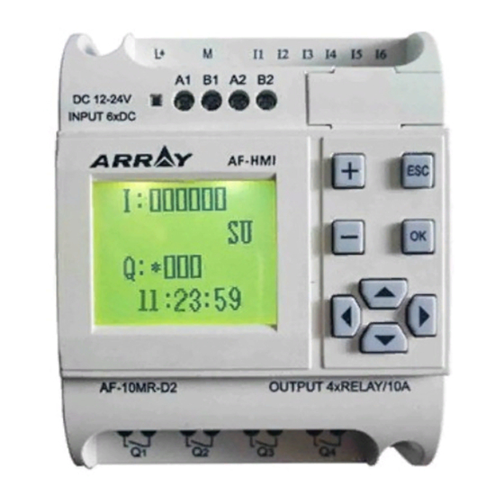
Now FABs are being widely used in many fields such as industry, com- merce, mining, agriculture, home automation etc. 1.1 Structure of FAB AF-10 FAB series 1 Power terminals 2 Input ports 3 Communication interface... -
Page 12: Parameters And Models
FAB I ntelligent ontrollerr AF-20 FAB series 1 Power Terminals 2 Input ports 3 Communication interface 4 Operating keys 5 Output ports (Output of relays or transistors) 6 LCD display panel 1.2 Parameters and models Item Type Power Input Output... - Page 13 hapter ntroduction to 12 points DC digital in- 8 points transistor output AF-20MT-E DC12-24V (equivalent NPN) 12 points DC(with ana- AF-20MR-D DC 12-24V 8 points relay output log) digital input 12 points DC (with ana- 8 points transistor output AF-20MT-D DC12-24V log) input (equivalent NPN)
-
Page 14: Features
FAB I ntelligent ontrollerr 1.3 Features 1. Removable programming panel with Liquid Crystal Display There is an operating panel with LCD display on the frontal side of FAB. You can use the operating keys on this panel to edit directly the control pro- gram for the FAB. - Page 15 hapter ntroduction to on-line testing and commissioning. The system can be proven before being put into actual service. QUICK II will not only guide you to implement the editing of the control programs, but will also perform the real-time monitor- ing for the field environment and the operational conditions of FAB.
- Page 16 FAB I ntelligent ontrollerr 9. Voice function For the first time, FAB puts voice recording and broadcasting functions into the automatic control industry, and creates an intelligent controller which can give audible voice outputs to finish voice prompt function. 10.Networking function FAB has a networking function.
-
Page 17: Chapter Ii Installation And Wiring
II I hapter nstallation and iring Chapter Ⅱ Installation and wiring 2.1 Installation 2.1.1 Methods FAB is small so it is suitable to be fit inside panels or machinery. The installa- tion of FAB is quite simple. 1. Use a standard DIN rail for the installation of FAB as shown in Fig. 2.1. 2. -
Page 18: Dimensions (Unit:mm)
FAB I ntelligent ontrollerr Fig. 2.2 Removing LCD panel as instructed 2.1.2 Dimensions (unit:mm) Fig. 2.3 AF-10 Series... -
Page 19: Wiring Of Fab
II I hapter nstallation and iring Fig. 2.4 AF-20 Series 2.2 Wiring of FAB A screwdriver with a spade tip width of 3mm is needed for the wiring of FABs. As for the cross section of a wire, the following two sizes are at choice : 1 x 2.5mm 2 x 1.5mm 2.2.1 Connection of power supply... -
Page 20: Fab Input Connection
FAB I ntelligent ontrollerr The power connection for FABs is shown in the following drawings: Fig 2.5 AC Type Fig 2.6 DC Type 2.2.2 FAB input connection A FAB input can be either switch, such as on/off switches etc., or analog, such as pressure, temperature, humidity, flow, etc. - Page 21 II I hapter nstallation and iring When the close current of a glow lamp is less than or equal to 0.2mA, it can be connected directly, and S w i t c h w i t h when the close current of a glow None glow lamp lamp is greater than 0.2mA, the...
-
Page 22: Fab Output Connection
FAB I ntelligent ontrollerr FAB input connection is shown as follows: Fig 2.7 AC Type Fig 2.8 DC Type(E Type) Fig 2.9 AC(D/GD Type) 2.2.3 FAB output connection Outputs of FABs like AF-10MR-A, AF-20MR-A, AF-10MR-D, AF-20MR-D, AF-10MR-E and AF-20MR-E are relays whose contacts are separated from the power supply and input ports;... - Page 23 II I hapter nstallation and iring The connection is shown as follows: Fig 2.10 Relay Output 2. Requirements for the transistor outputs Transistors can be classified as D transistors and GD ones. The load connected to FAB must have the following characteristics:When the switch is ON (Q=1), the maximum current is 2A.
-
Page 24: Fab Network Connection
FAB I ntelligent ontrollerr Note: 1.“L+” line should be connected to “L+” of FAB Power supply, and the load should be directly connected to the “M-” of the load power. 2.The load voltage should be not more than DC80V. 2.2.4 FAB network connection 485 Power Bus (5V) 485 Message Bus AF-C485/D485... - Page 25 II I hapter nstallation and iring MEMO...
-
Page 26: Chapter Iii General Descriptions For Function Blocks
Chapter Ⅲ General Descriptions for Function Blocks FAB series products adopt the programming method by the use of twenty kinds of FBs (function blocks), each of which is able to independently implement a specific controlling function like time-delay On, time-delay Off, Switch time setting and counting. -
Page 27: And
Ⅲ G hapter eneral escriptions unction locks Dual commutator contact Parallel connection of NC NAND contacts Serial connection of NC con- tacts 3.1.1 AND The symbol of AND is shown in The electrical line diagram for serial the follows: connection of a certain number of NO contacts is shown as follows: This function block is called AND, because only when all of I1, I2 and I3 are in status 1, the status of Output Q will be 1 (i.e. -
Page 28: Not
FAB I ntelligent ontrollerr 3.1.2 OR The electrical line diagram for the parallel The symbol of OR is shown in connection of a certain number of NO con- the follows: tacts is shown as follows: This function block is called OR, because the status for at least one of inputs I1 or I2 or I3 is 1 (i.e. -
Page 29: Nand
Ⅲ G hapter eneral escriptions unction locks Logical frame of “NOT”: 3.1.4 NAND The electrical line diagram for paral- T he sy mbol of NA N D in FA B is lel connection of certain number of shown as follows: NC contacts is shown as follows This function block is called NAND, because only when all of I1, I2 and I3 are in status 1 (i.e. -
Page 30: Xor
FAB I ntelligent ontrollerr Only when all the inputs of NOR function blocks are at a low potential (status 0), the output will be closed (status 1). If any input is at high potential (status 1), the output will be open (status 0). Logical frame of “NOR”: 3.1.6 XOR As shown in the line diagram, In... -
Page 31: Special Function Blocks (Sf)
Ⅲ G hapter eneral escriptions unction locks Logical frame of XOR: 3.2 Special function blocks (SF) Function Representation Graphic DPR (ON time delay) DDR (OFF time delay) PLR (Pulse relay) CW (Clock switch) RS (RS relay) (Clock pulse generator) -
Page 32: Rpr
FAB I ntelligent ontrollerr RPR (Hold ON time-delay relay) UCN (Up-counter) DCN (Down- counter) MPLR (Single pulse time relay) TEL (Telephone dialing block) AN (analog input block) PLAY( Broadcast voice section & Selector switch locks) MR (Recording voice sec- tion & Selector switch) - Page 33 Ⅲ G hapter eneral escriptions unction locks 3.2.1 DPR Line diagram/Symbol in FAB Description After TRG is triggered, the time delay timer starts timing. (If TRG stops trig- input TRG gering during the timing of timer, the timer will terminate the timing). After time T, the output is on (the output Pa r a meter signal transforms from 0 to 1).
- Page 34 FAB I ntelligent ontrollerr 3.2.2 DDR Li ne d iag ra m /Sy mbol i n Description Turn on the timer of the time-delay off re- lay when the input TRG (trigger) is at the Input TRG descending edge (changing from 1 to 0) The timer of disconnecting time-delay re- lay is reset via R (Reset Input), and Output Input R...
- Page 35 Ⅲ G hapter eneral escriptions unction locks 2. If Input TRG changes from Status 1 to Status 0 again, the timer is activated again. 3. Before the set time T is over, the timer and output can be reset via R (Reset) input.
- Page 36 FAB I ntelligent ontrollerr Descriptions: 1.Every time the trigger input TRG changes from status 0 to Status 1, the status of Output Q will change accordingly (The status of Q will be reversed). 2. Reset Q to Status 0 via Input R. 3.
- Page 37 Ⅲ G hapter eneral escriptions unction locks The above arrangements are correct, while the below arrangements are wrong: On: May 1st, 2000 19:00 Off: May 1st, 2000 18:00 On: Apr. 2nd, 2000 8:00 Off: Apr. 2nd, 2000 5:00 During the time setting of the time switch, if two time-points (on and off) are set, the output is on only in this period, that’s, time from on to off.
- Page 38 FAB I ntelligent ontrollerr Note: You can directly set time as follows by using Quick II, the programming Software. MO: 6:00 TU: 8:00 The PC directly transforms this to above-mentioned logic form and then transmits the form to a FAB, which is invisible to users. 3.
- Page 39 Ⅲ G hapter eneral escriptions unction locks 8:00 24:00 24:00 5:00 Notes: MO: Monday MO-SU: every day from Monday to Sunday TU: Tuesday MO-TH: every day from Monday to Thursday WE: Wednesday MO-FR: every day from Monday to Friday TH: Thursday MO-SA: every day from Monday to Saturday FR: Friday FR-SU: every day from Friday to Saturday...
- Page 40 FAB I ntelligent ontrollerr 9:00 11:00 OFF Q1 (ERROR) 6:30 ON 8:30 OFF Note: This phenomenon follows the principle that latter commands surpass for- mer ones. 6. When the week system is selected, if ON is set at 8:00 and Off is set at 9:00 from Monday to Thursday (MO~TH), then FR, SR and SU will maintain their former status ,that’s, the original ON status will keep ON while the original OFF status will keep OFF.
- Page 41 Ⅲ G hapter eneral escriptions unction locks 3.2.5 RS Line diagram/Symbol in FAB Description Set Output Q to 1 via Input S (Set). S port Input S can receive two-tone signal input such as P0~P9 phone signals. Set Output Q to 0 via Input R (Reset). If S Input R and R are 1 at the same time, the Output Q is 0 (with R having a priority to S).
-
Page 42: Set (Set Password And Time)
FAB I ntelligent ontrollerr REMARK Status remains the original value Reset Reset (taking priority over Set) 3.2.6 CPG (clock pulse generator) Line diagram/ Symbol Description in FAB Make the CPG ON or OFF via Input EN Input EN (Enable). Input R Make Output Q be 0 via Input R (Reset). - Page 43 Ⅲ G hapter eneral escriptions unction locks Time sequence frame is as follows: Notes: 1. Use Parameter T to set ON/OFF time. The assignment range of T is 0.01 ~ 99.99, and the time units can be set respectively to hour (H), minute (M) and sec- ond (S).
- Page 44 FAB I ntelligent ontrollerr Time Sequence Frame: Notes: 1. If the status of Input TRG changes from 0 to 1, the internal timer will be acti- vated. When time T is over, Output Q becomes 1 and then the returned input TRG has no effect on output Q .Only when Input R becomes 1 again Output Q and Timer T will be reset to 0.
- Page 45 Ⅲ G hapter eneral escriptions unction locks Time Sequence Frame(PAR=5): Note: This function is applicable to the cases that counting is required. 3.2.9 DCN Line diagram/Symbol Description in FAB R takes priority over other inputs. When R in- Input R puts a reset signal, the counter is reset to 0 and output Q resets simultaneously.
- Page 46 FAB I ntelligent ontrollerr 3.2.10 MPLR (Single-pulse time relay) Line diagram/Symbol Description in FAB Trigger an input to activate the single-pulse Input TRG time relay. When the leading edge of TRG comes, a pulse with the duration of T is out- put.
- Page 47 Ⅲ G hapter eneral escriptions unction locks 3.2.11 Tel (The Voice Module needs to be used in conjunction with FAB) Figure Description The following input ports are at choice: I1 ~ IC, Q1 Input ~ Q8, HI, LO, M00 ~ M126, P0 ~ P9. When the output is 1, the telephone number of out- put port will be dialed to output.
- Page 48 FAB I ntelligent ontrollerr Step 1: Use the external telephone to dial the telephone numbers of the FAB- connected telephones, to connect FAB, and then you will hear the voice prompt as “please enter the password”. Step 2: Enter the password of the FAB correctly. Step 3: Dial P0 - P9 controlling signals to control the output of FAB.
- Page 49 Ⅲ G hapter eneral escriptions unction locks 3.2.13 MR (The Voice Module needs to be used in conjunction with FAB) Figure of FAB Description When ON is 1, record for the voice sec- tions starts. The following inputs are at opt ion :I1 - IC, Q1 - Q8, H I, LO, M00~M126, X.
- Page 50 FAB I ntelligent ontrollerr 3.2.14 AN Description Figure in FAB Comparative input port 1, with 0.0~10.0, I1~IC Input 1 to be selected. input1 Input 2 Function selection <,>,>,<,=,≠ -output inout2 input3 Comparative input port 2, with 0.0~10.0, I1~IC Input 3 to be selected.
- Page 51 Ⅳ P hapter rogramming on panel ChapterⅣ Programming on FAB panel The programming of a FAB is available for two methods : one way is to do the operation directly on a LCD panel, and the other one is to program by using QUICK II, the programming software, on a PC.
- Page 52 FAB I ntelligent ontrollerr a. Select the input/output or function block with keys; b. Press OK key to confirm the selection; c. Press ESC key to return to the previous step. 4.1 FAB status display After the power supply is switched on, the LCD panel will display a frame (Fig. 4.2), which is the Status Display Frame: The upper line I contains the status values of inputs 1 ~ 6.
- Page 53 Ⅳ P hapter rogramming on panel Note: The default password is 0001. 4.3 Function The editing frame is shown in Fig4.4. The user can use keys to move the arrow > on the left and press the OK key to confirm the selection of functions, four types of which are: Editor: The function for programming editing.
- Page 54 FAB I ntelligent ontrollerr 4.3.1.1 Edit PRG/New Prg The Edit PRG Menu Frame is shown in Fig. 4.6 and the function blocks are to be selected under this menu. >AND NAND Fig 4.6 Select a Function Block The user may use the keys to move the arrow >...
- Page 55 Ⅳ P hapter rogramming on panel After the selection of Input/Output PIN, press OK to enter the Parameter Setting Status, shown at the top left corner of Fig. 4.7. Firstly move the cursor to “I” po- sition, which is at the top left corner, with keys, and then change the to- be connected types (I, Q, H, L, X, M, P), and press OK to confirm the changes.
- Page 56 FAB I ntelligent ontrollerr The first line:Block number and timing mark The second line: time units— HOU (Hour), MIN (Minute), SEC (second) The third line: Setting integer of time (00-99) The forth line: Setting decimal of time (00-99) 2. Function blocks with counting function include: UCN: Up Counter DCN: Down Counter.
- Page 57 Ⅳ P hapter rogramming on panel The first line: the day system The second line: year, month and day The third line: the output ON time (T1) The forth line: the output OFF time (T2) 2) If the week system W is selected, the following will be displayed on the LCD panel: Week Fig.
- Page 58 FAB I ntelligent ontrollerr Note If the week system is selected, then only T1 and T2 need to be set because the system will ignore D whether it has been set or not. 4. Set the Telephone Blocks When a Telephone Block is selected, LCD panel will be displayed as Fig. 4.13 shows.
- Page 59 Ⅳ P hapter rogramming on panel 5. Set the AN block AN block is shown as follows: Input 1 Input 2 Input 3 Input 1: Input I and Input K are available for options. (1) Input I means this port is connected to FABs input, whose assignment range is I1~I6 (AF-10 series) and I1~IC (AF-20 series).
- Page 60 FAB I ntelligent ontrollerr 2. In the above frame 000 is the original value. You can press select the block number and then press OK to confirm your selection. The range of inserted block number is from 001 to the maximum number of the current program.
- Page 61 Ⅳ P hapter rogramming on panel 2. In the above frame 000 is the original value. You can press select the block number, and then press OK to confirm your selection. The range of block number for Delete FB is from 001 to the maximum number of the cur- rent program.
- Page 62 FAB I ntelligent ontrollerr 4.3.2 FAB/Rom There are three options in Select FAB/Rom Frame, as shown in Fig. 4.19. >FAB( XXXX Rom FAB Addr Modern Fig. 4.19 FAB (XXXX): (The series number of a FAB system service) Rom→FAB: read the program from a FAB FAB-Addr: view or modify a FAB address MODEM: initializing MODEM 4.3.2.1 Read program from FAB (Rom...
-
Page 63: Edit A Fab Function Program
Ⅳ P hapter rogramming on panel 10:49:04 Set Real Time Clock (hour: minute: second) Set Date (year: month: day) 2000/06/02 Day SU Set Week Set password 5678 Fig. 4.21 Set Password Frame 4.4 Edit a FAB function program During the editing of a FAB function program, special attention need be paid to some programming rules, the application of the mid-relays and how to use FAB’... - Page 64 FAB I ntelligent ontrollerr Example: (M02) cause block B03 Result block B04 Fig. 4.22 Rule 3: In a program path, an output may be connected to the lead input (for number transfer), but the block with a smaller sequence number shall be used as the lead input (cause block), while the one with a greater sequence number shall be the result block.
-
Page 65: Intermediate Relay
Ⅳ P hapter rogramming on panel 4.4.2 Intermediate relay During the programming, the intermediate relay is a very important part which acts like a bridge. The intermediate relay of a FAB is similar to that in the relay control system. They can store some intermediate status and then transfer it to a block requiring this status for input. - Page 66 FAB I ntelligent ontrollerr 2. When the sound sensing switch is on, the light will be turned on and keeps this state for 2 minutes. The Function Block Diagram for the mentioned control function is as follows: Fig. 4.24 The following steps should be followed in the programming of this control function on FAB operation panel: Step I: Enter FAB Editor Frame 1.
- Page 67 Ⅳ P hapter rogramming on panel 3. Input the password (assume the password is 2165); Press twice and the first digit value of the password will change to 2; Press right moving key and the cursor will move to for the second digit of the password value to be input;...
- Page 68 FAB I ntelligent ontrollerr >AND NAND >RS Fig. 4.29 2. Select and set the first function block: Move > to the position of RS relay with and press OK to enter the Function Block Set Status with the cursor at the top input Link. The following will be on LCD panel: Fig.
- Page 69 Ⅳ P hapter rogramming on panel Then the value of this parameter needs to be set by pressing For example; if I1 is to be set, just press key when I1 is displayed, as shown in Fig. 4.31 (the variation range of I is I1-I6 or I1-IC). Press to move the cursor to position S and then press to set the S...
- Page 70 FAB I ntelligent ontrollerr 3. Select and set the second function block Press to return to the Function Block Selection List Frame and select the second function block. Move “>” to the position of DDR function block and press . Now you can set the parameters for this function block.
- Page 71 Ⅳ P hapter rogramming on panel Press to move the cursor to position T and press to enter the Set Timer Frame. The following will be displayed on the LCD panel: B02:Time Hou:Unit 02:Int 00:m Fig. 4.37 Press to enter the Time Unit Selection Status. Now the options can be changed with .
- Page 72 FAB I ntelligent ontrollerr 4. Select and setup the third function block Press to return to the Function Block Selection List Frame and select the third function block. Move > to the position of OR function block and press . Now you can set the parameters for the third function block.
- Page 73 Ⅳ P hapter rogramming on panel The following will be on the LCD panel: Fig. 4.43 Move the cursor to the output link with and press After selecting Q in the parameter list, press and set the said output Pin to be Q1 with .
- Page 74 FAB I ntelligent ontrollerr 2. Move“>” to RUN and press . Then the following will be on the LCD panel: 15:45:10 Fig. 4.46 3. It means that the program is now written into FAB and can be run according to the new program. Notes: How to read and modify the current program 1.
- Page 75 Ⅳ P hapter rogramming on panel MEMO...
-
Page 76: Chapterv The Voice Module
FAB I ntelligent ontrollerr ChapterⅤ The Voice Module FAB has three important special functions: Voice alarm function, telephone control function, and auto-dialing. Without the help of the Voice Module, all of the three functions are not able to be implemented. 5.1 The structure of the voice module Fig 5.1 1. -
Page 77: Connection Between Voice Module And Fab
TEL socket. Connect the Voice Module and FAB by using the special connection (Note: using the special part of FAB series) in fig- ure 5.2. For convenient installation, there is a DIN rail clamp on the bottom of the Voice Module. - Page 78 FAB I ntelligent ontrollerr Section 3: the prompt voice message for playing when the Voice Module dials to the external telephone. 2. Section 4-98: the voice messages used for programming. The user can play any of these sections, all according to their needs. But if they want to record some of them, it needs to begin with section 0 and among the recorded sections section0,section1,section 2 and section 3 are for voice system.
- Page 79 hapter oice odule If you don’t input * key in 60 seconds, the Voice Module will ring off. If he in- puts * key the Voice Module will keep mute for 10 seconds, and you must input the 4-digit password within this 10 seconds. If you do not input the password or inputs a less-than-4-digit password within 10 seconds Voice Module will play section 0 again.
-
Page 80: Recording
FAB I ntelligent ontrollerr 5.4 Recording The recording function of Voice Module is similar to a recorder. There are two methods for recording: on-line recording and manual recording. A) Recording on line The first step: Firstly, connect the Voice Module to FAB, then plug one terminal of recording line into the PC, and plug the other into the recording port of the Voice Module. - Page 81 hapter oice odule Fig 5.4-3 The fifth step: the prompt frame of “setting the Voice Module type” is shown in Fig. 5.4-4. Fig 5.4-4 Note: 1. The sampling frequency for 4 minutes recording is 3.4 KHz, while for 6 min- utes one the frequency is 2.3 KHz, and for 8 minutes 1.7 KHz.
- Page 82 FAB I ntelligent ontrollerr Fig. 5.4-5 The seventh step: the prompt frame of “copy voice to MUL” is shown in Fig. 5.4-6. Fig. 5.4-6 The eighth step: choose the right communication port, and then click the “open” item, to choose a recording voice file, as shown in Fig. 5.4-7. Fig.
- Page 83 hapter oice odule The ninth step: first click “open” button and then “start copy” button. The copy course is shown in Fig. 5.4-8. Fig. 5.4-8 The tenth step: the prompt frame for confirming is shown in Fig. 5.4-9, and click OK button.
- Page 84 FAB I ntelligent ontrollerr Fig. 5.4-10 The second step: on the interface of QUICK II software, make a recording pro- gram. B1 is to set section 99, which means all the voice sections in the Voice Module are cleared up; while B2 is to set section 0, which means recording sec- tions begin from section 0.
-
Page 85: Sound Broadcasting
hapter oice odule cording indicator light is on, you should say “please enter the password” into MIC. After that, turn on switch K4 for 1 second and then off, you will hear the above re- cording section “please enter the password” is played by the Voice Module, which means section 0 has been recorded into Voice Module successfully. -
Page 86: Update "Set Message No." Online
FAB I ntelligent ontrollerr 5.6 Update “set message No.” online 1) Firstly connect FAB to a PC, and then click “Option—Set first voice message” , as shown in Fig. 5.6-1. Fig. 5.6-1 2) The prompt frame is shown as below: Fig. - Page 87 hapter oice odule Fig. 5.7-1 2) The prompt frame is shown as below: Fig. 5.7-2 You must first input FAB password, then you can enter the password interface of Voice Module. After inputting the FAB password, then click OK button. 3) The prompt frame is shown in Fig.
-
Page 88: Update "Incoming Call" Online
FAB I ntelligent ontrollerr 5.8 Update “incoming call” online 1) Firstly connect FAB to a PC, and then click “Option >Incoming call”, as shown in Fig.5.8-1. Fig.5.8-1 2) The prompt frame is shown in Fig. 5.8-2. Fig.5.8-2 With the dialogue box, select Yes or No to confirm whether incoming calls is accepted or not. - Page 89 hapter oice odule Fig. 5.9-1 FAB has a RS block which can be driven by the double-tone information, so you only need to write the RS block program driven by Signal P0-P9 into FAB and it will work. For example, you control on-off for output Q1 by the telephone keys. (Note: set Voice Module password for dialing in and out to avoid illegal opera- tion by others).
-
Page 90: Automatic Dialing Function
FAB I ntelligent ontrollerr 2) Enter the correct password and enter * key first, and then you will hear the voice section 1 as “correct password, please enter the control code”, and the Voice Module also plays section 1 simultaneously. 3) Control output Q1 by telephone key: enter *0 to open Q1, and enter *1 to close Q1 (* key must be input before inputting the digital keys) 4) Enter # twice to ring off the telephone. -
Page 91: Example For Voice Module
hapter oice odule Fig. 5.10-1 5. Write your program into FAB Description: when a thief breaks into your room, I1 is activated. At the same time Voice Module auto-dials the police-calling number and broadcasts “thief found in my house and enter *0 key to ring off” in the telephone. You need to set the volume of indoor Voice Module to the lowest level in order for the thief not to hear the sound. - Page 92 FAB I ntelligent ontrollerr To perform the above control, set the voice sections as below: Section 0: Please enter your password Section 1: Correct password, please enter the control code Section 2: Wrong password, please re-enter Section 3: Catch a thief Section 4: Open for the air-condition Section 5: Close for the air-condition Steps:...
- Page 93 hapter oice odule Firstly, you should connect FAB to Voice Module and record voice sections. Then write your program into FAB. When dialing into the Voice Module, you will hear the prompt voice “please enter the password”. After inputting the cor- rect password, you will hear the prompt voice “correct password, please enter the control code”.
- Page 94 FAB I ntelligent ontrollerr...
- Page 95 Ⅵ A hapter pplications ChapterⅥ Applications FAB has a wide application range. For your good knowledge of its application fields and your convenience of using it, in this chapter we will list some common but representative control schemes, which will show you the convenience and simplicity of auto-control by using FAB, especially the auto-control in a system requiring time control and an intelligent living zone.
- Page 96 FAB I ntelligent ontrollerr When FAB is used for this control, it will be very simple both in the connection of the external line and in editing the program. If QUICK II, the programming soft- ware, is used for editing the control program, it is only necessary to set two time switch blocks.
- Page 97 Ⅵ A hapter pplications 6. 2 The multi-function switch for lights in stairs and halls Control requirements: 1. When you press the switch, the light is turned on, and will be automatically turned off after 3 minutes. The light will twinkle for 5 seconds before the turn- off.
- Page 98 FAB I ntelligent ontrollerr 6. 3 Auto-gate control Control requirements: 1. Opening and closing of the gate should be controlled by the guard in the control room. 2. Normally the gate shall be opened or closed completely, but the opening and closing action can be interrupted at any time.
- Page 99 Ⅵ A hapter pplications 6.4 Ventilation system Control requirements: The ventilation system shall be able to send fresh air into the room as well as ex- haust the waste gas out of the room. 1. Waste gas exhaust unit and fresh air forced-draft unit must be installed in the room.
- Page 100 FAB I ntelligent ontrollerr 6. 5 The neon lamp control system 1. Display mode, for example: Array Electronics welcomes you ! 1. 1 Display “Array” 1. 2 Display “Electronics” 1. 3 Display “welcomes you!” 1. 4 Cycle 1.1-1.3 2. Control requirements (1) It should be automatically turned on at 18:00:00 and turned off at 23:59:59 every day.
- Page 101 Ⅵ A hapter pplications The program dialogue is as below: 6. 6 The Illumination system for display windows Control requirements: 1.1 The display time Monday to Friday 8:00~22:00 Saturday 8:00~23:59:59 Sunday 9:00~20:00 1.2 Requirements for the illumination during display time a.
- Page 102 FAB I ntelligent ontrollerr b. The strong lighting Open the basic lighting equipments and additional ones; Close the non-display lighting equipments; 1.3 Requirements for the illumination during non-display time Close the basic lighting equipments and additional ones; Open the non-display lighting equipments; 1.4 Test switch All the lamps will be turned on when the switch is pressed.
- Page 103 Ⅵ A hapter pplications 6.7 The building management Control requirements: 1. Automatically read various meters which includes the watt-hour meter, water meter and gas meter 2. Proof against fires and protect against thieves; 3. Control the start and stop of relevant electrical equipments. FAB can flexibly meet the needs of the automatic building control in a modern in- telligent living zone as well as realize a central monitoring.
- Page 104 FAB I ntelligent ontrollerr I5- connected to the water meter I6- connected to the gas meter I7- connected to the watt-hour meter Output parts: Q1- connected to the air-condition equipment Q2- connected to the ventilation equipment Q3- connected to the alarm equipment The application of FAB in a voltage diode counting and packing assembly line The control requirement and configuration:...
- Page 105 Ⅵ A hapter pplications Control System Figure is as blew: 80v- 2000v- 1000v- 500v- 1500v- Resisting Resising Resisting Resising Resisting Assembly Line Assembly Line Assembly Line Assembly Line Assembly Line MEMO...
- Page 106 FAB I ntelligent ontrollerr MEMO...
- Page 107 echnical arameters Technical Parameters 1.1 General technical parameters Item Basis Condition Climate environment Cold: IEC68-2-1 Humidity Heat: IEC68-2-2 Horizontal installation -20 ~ 70 C Vertical installation -20 ~ 70 C Storage/transportation -40 C ~ +70 C Relative humidity IEC68-2-30 5% ~ 95% without condensation 795 ~ 1080kpa Atmospheric pressure 10cm...
- Page 108 FAB I ntelligent ontrollerr 25 C clock buffer memory Typical 100h RTC accuracy ±Max 5S/day 1.2 AF-10MR-A / AF-20MR-A Power Supply The rated voltage of power supply AC100-240V Allowable range of the rated input voltage AC 85V ~ 260V VDE0631: AC 85V ~ 260V IEC1131: 47 ~ 63Hz...
- Page 109 echnical arameters Fluorescent Light Tube Without Compensation 10 x 58W (AC230/240 V) (25,000 Switch Cycles) Power Supply Protection B16 Short Circuit Protection cos 1 600A Short Circuit Protection Power Supply Protection B16 cos 0.5 ~ 0.7 900A Max. 20A Output Relay Protection Feature B16 Switch Frequency 10Hz...
- Page 110 FAB I ntelligent ontrollerr Transistor output (equivalent NPN) Output Type Output Voltage <DC80V Max. 2A Output Current Short Circuit and Overload Protection Circa 2A Current limit of short circuit No (even in the whole temperature Reduction of the rated value range) 1 .4 AF-10MR-D/AF-20MR-D Power Supply...
- Page 111 echnical arameters Fluorescent Light Tube With 10 x 58W Electrical Controller (25,000 Switch Cycles) Fluorescent Light Tube With Regular 1 x 58W Compensation (25,000 Switch Cycles) Fluorescent Light Tube Without Compensation 10 x 58W (25,000 Switch Cycles) Power Supply Protection B16 Short Circuit Protection cos 1 600A Power Supply Protection B16...
- Page 112 FAB I ntelligent ontrollerr Delay time From 1 to 0 Typical 50ms From 0 to 1 Typical 50ms The length of power line(without shield) 100m Output type Transistor output (equivalent NPN) Output Voltage <DC80V Output Current Max. 2A Short Circuit and Overload Protection Current limit of short circuit Circa 2A No (even in the whole temperature...
- Page 113 echnical arameters Fluorescent Light Tube With 10 x 58W Electrical Controller (25,000 Switch Cycles) Fluorescent Lig ht Tube Wit h Reg ula r Compensation (25,000 Switch 1 x 58W Cycles) Fluorescent Light Tube Without Compensation (25,000 Switch Cycles) 10 x 58W Short Circuit Protection cos 1 Power Supply Protection B16 600A Short Circuit Protection cos 0.5 ~ 0.7...
- Page 114 FAB I ntelligent ontrollerr Input current of signal 1 <0.3mA Delay time From 1 to o Typical 50ms From 0 to 1 Typical 50ms Length of Power Line (Without Shield) 100m Digital output Output Type Transistor output (equivalent PNP) Output Voltage <DC80V Output Current Max.
- Page 115 uality uarantee Quality Guarantee Quality Array Electronics Co., Ltd (abbreviated to ARRAY hereinafter) promises that this product has been strictly tested before its delivery from our plant and com- plies with all the all product requirements listed in this manual. Once properly installed, it will work in accordance with its specifications.
- Page 116 FAB I ntelligent ontrollerr FAB2 PLC series 1.1 Structure of FAB2(take 10 point for instance) ① Power input ② Input terminals ③ Power indicator(blink once a second,red indicator) ④ 485 communication port ⑤ Program port ⑥ Operating keys ⑦ LCD display panel ⑧...
- Page 117 ontents Type Type Power Input Output 12 points AC AF-20MR-A2 AC100-240V 8 points relay output input 12 points AC/DC AF-20MR-E2 AC/DC12-24V 8 points relay output input 12 points DC 8 points transistor AF-20MT-E2 DC12-24V input (NPN)output 12 points DC AF-20MR-D2 DC12-24V input (with 8 points relay output...
- Page 118 FAB I ntelligent ontrollerr 1.4 Analog calibration (1) Press OK and ESC simultaneously and enter FAB2 password to jump into the function interface, select FAB/ROM ok, and then press OK and → keys to calibration interface, each channel must be calibrated separately(AI0 said I1).
- Page 119 ontents The description of address types used in SH300 software: Object Address Address range Read/write Description type type 1~12 Read Read input status 1~8 Read Read output status The number of Indicator the corresponding Read the output status auxiliary relays in Read of the function block in FAB2 program (0...
- Page 120 FAB I ntelligent ontrollerr 2) Modbus RTU(A1B1) MODBUS RTU Introduction Address Function remark type code Only read Read system status (00-FF) Only read Read digital inputs status (100-1FF) Only read Read analog input AI status (300-3FF) Only read Read output Q status (200-2FF) Note 1:Fab2 is act as modbus slave device, which responds according to the requested data by modbus master device.
- Page 121 ontents 1.6 Comparison table FAB2015 Digital input 6/12 6/12 I/O points Digital output Memory 64k/127blocks 64k/127blocks Supply voltage DC12-24V/AC110-220V DC12-24V/AC110-220V Extension module none none general characteristics Programming language Timer number Counter number Password protection 25℃ RTC buffer 120h 160h RTC accuracy 150s/month 20s/month Program between new and...
Need help?
Do you have a question about the FAB Series and is the answer not in the manual?
Questions and answers