Table of Contents
Advertisement
Quick Links
SH-300 User's Manual
Contents
1 SH-300 Hardware part .......................................................................................... 3
1. 1 System General Introduction ....................................................................... 3
1. 2 Specification Parameter............................................................................... 3
1. 3 Hardware Structure .................................................................................... 4
1. 4 Function Key List ........................................................................................ 7
1. 5 Installation Dimensions and Guide ............................................................. 8
2 SH300 Software Part .......................................................................................... 11
2. 1 SH300 General Introduction ...................................................................... 11
2. 2 Process Chart ............................................................................................ 11
2. 3 Installation and Uninstallation of SH-300 ................................................... 12
2.3.1 Installation of SH-300 ....................................................................... 12
2. 4 Operation Interface .................................................................................... 16
2.4.1 File ................................................................................................. 18
2.4.2 Edit ................................................................................................ 18
2.4.3 View ............................................................................................... 19
2.4.4 Screen ........................................................................................... 20
2.4.5 Object ............................................................................................ 21
2.4.6 Connect ......................................................................................... 22
2.4.7 Tool ................................................................................................ 22
2.4.8 Help ............................................................................................... 23
2. 5 Operation Instruction ................................................................................. 24
2.5.1 Indicator ......................................................................................... 24
2.5.2 Function Key .................................................................................. 25
2.5.3 Static text ....................................................................................... 26
2.5.4 Dynamic text .................................................................................. 27
2.5.5 Register ......................................................................................... 28
2.5.6 Bar Graph ...................................................................................... 31
2.5.7 Trend Graph .................................................................................. 32
2.5.8 Bitmap ........................................................................................... 33
2.5.9 Message Display ........................................................................... 34
2.5.10 Alarm List ....................................................................................... 35
2.6 User-defined SH300 system information ................................................... 37
2.7 Multi Language Editor ................................................................................ 47
2.8 Operation Example .................................................................................... 49
3 Manipulation ....................................................................................................... 56
3. 1 Download Window .................................................................................... 56
3. 2 Communication ........................................................................................ 56
3. 3 Shifting the windows ................................................................................. 57
..........................................................................................
Page 1 of 103
Contents
15
Advertisement
Table of Contents

Related Manuals for Array electronic SH-300


Summary of Contents for Array electronic SH-300
-
Page 1: Table Of Contents
1. 5 Installation Dimensions and Guide ............. 8 2 SH300 Software Part ..................11 2. 1 SH300 General Introduction ..............11 2. 2 Process Chart .................... 11 2. 3 Installation and Uninstallation of SH-300 ........... 12 2.3.1 Installation of SH-300 ............... 12 2.3.2 Uninstallation of SH-300 .................. - Page 2 4.13 Emerson EC20 Series ................74 4.14 KDN-K3 Series ..................75 4.15 HITACHI MICRO-EH Series ..............76 4.16 MODBUS RTU/ASCII and RTU/ASCII EXTEND protocol ....... 77 4.17 SH-300 Freedom Protocol ..................4.18 Array FAB Series PLC ................90 4.19 Array SR Series PLC ................93 4.20 Array TC-Pro Series Digital Timer/Counter/Tachometer ......
-
Page 3: Hardware Part
SH-300 Hardware part 1.1 System General Introduction SH-300 is a small Human-Machine interface, mainly being used to be connected with PLC or other intelligent controllers with COM port communication function. It can monitor, setup and modify the data of the register or the status of the relay inside the PLC; thereby manipulators can monitor conveniently the PLC or the running status of the intelligent controllers with COM port communication function. -
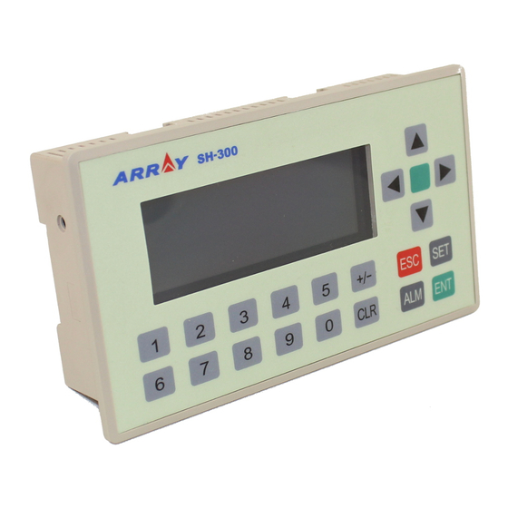
Page 4: Hardware Structure
1.3 Hardware Structure The front panel of SH-300 is as shown in the following figure. There is the 4.3’’STN LCD display at the top left corner. At the top right corner and the bottom there are 20 thin-film switch keys, which have a good handle and a long life. - Page 5 Special function of keys: Bit setting, Bit resetting and Screen jumping etc. On the right side of SH-300 there are power terminal and COM port and on the left side there is a contrast potentiometer. Refer to the following figure for details.
- Page 6 The display of SH-300 is with LED background light. Press any key, the background light will be turned on automatically. The backlight will be turned off automatically if there is no operation in the minutes .Users can modify the turnoff time of the background light in SH300 software and...
- Page 7 SH-300 User’s Manual Hardware Part Page 7 of 103...
-
Page 9: Function Key List
SH-300 User’s Manual Hardware Part 1.4 Function Key List Function [←] When modifying the register data, the cursor will be moved one-digit left. [→] When modifying the register data, the cursor will be moved one-digit right. To jump to the previous screen, whose number is set in the screen property option. -
Page 10: Installation Dimensions And Guide
SH-300 Text Panel 1.5 Installation Dimensions and Guide Dimensions of SH-300 (L*W*H): 171.8×98.8×38.6 (Unit: mm) Dimensions of the installation hole: 165×85 (Unit: mm) Method 1: Embedded installation The installment surface must be up to Standard Type 4, being applicable for indoor or the switchboard box on coequal condition. - Page 11 SH-300 User’s Manual Hardware Part Method 2:DIN rail installation(standard 35mm DIN rail installation) Method 3: Screw installation (To install on the motherboard) Page 11 of 103...
- Page 12 SH-300 Text Panel 《Memo》 ————————————————————————————— ————————————————————————————— ————————————————————————————— ————————————————————————————— ————————————————————————————— ————————————————————————————— ————————————————————————————— ————————————————————————————— ————————————————————————————— ————————————————————————————— ————————————————————————————— ————————————————————————————— ————————————————————————————— ————————————————————————————— ————————————————————————————— Page 12 of 103...
-
Page 13: Sh300 Software Part
SH300 Software Part 2.1 SH300 General Introduction SH300 is the special development software of SH-300 Programmable Text Display, which is run on the base of WINDOWS 98/2000/XP platform. SH300 software makes the best use of the abundant graphic interface and the object-faced design of WINDOWS, which makes it convenient for the users edit the required control screens and the alarm interfaces in a short time. -
Page 14: Installation And Uninstallation Of Sh300
SH-300 Text Panel 2.3 Installation and Uninstallation of SH300 2.3.1 Installation of SH300 The installation of SH300 is very simple. In the installation process, a prompting dialogue box will appear automatically and you will complete the installation smoothly on the computer under its guidance. - Page 15 SH-300 User’s Manual Software Part 3. Fulfill the interface with the correct information and click NEXT to enter the installation path setting interface as follows: ▲ Click NEXT, the SH300 software will be installed in the default path as shown. If it is necessary to select the path, click BROWSE to reset the desired path.
- Page 16 SH-300 Text Panel Note: Selection of Typical option is recommended. 5. Select NEXT to enter the program aggregate displaying window as in the following diagram: ▲ Click Next to start the installation program; ▲ Click Back to return to the previous interface;...
-
Page 17: Uninstallation Of Sh300
SH-300 User’s Manual Software Part 2.3.2 Uninstallation of SH300 There are two ways for the uninstallation of SH300: 1. Remove from WINDOWS START MENU ▲ Under the WINDOWS taskbar, click Start→Program→ARRAY→SH300→Unistall of SH300 As shown in the following diagram: ▲ When a confirm uninstall dialogue box appearing, click Yes and the following remove interface will appear. -
Page 18: Operation Interface
Copy the current screen Set relative parameter of SH-300 Text Display Login in alarm list information, each piece of alarm information correspond to a status of a middle relay Download the project into SH-300 via communication cable Page 18 of 103... - Page 19 Software Part Indicator: displaying on/off status of PLC inner middle relay Function key: 14 keys on SH-300 panel being able to be defined as function keys, whose functions are screen-jumping and switch control etc. Static text, including Chinese characters, English characters and characters from other operation system Dynamic text, text content being able to be changed by PLC’s register.
-
Page 20: File
SH-300 Text Panel 2.4.1 File This instruction is mainly used for project file management, including creating, opening, saving etc Menu Name Function New project Create a new project file Open project Open an old project file Save project Save the current project file... -
Page 21: View
SH-300 User’s Manual Software Part Menu Name Function Cut components Copy Copy components Paste Paste components Delete Delete components Select All Select all components Control Change the arrangement Position Set alignment type Save Screen Bitmap Save the current screen as graph format... -
Page 22: Screen
The “SH300 Config(S)…” option is used to set relative parameter of SH-300, such as set the boot screen number (the default screen number is 1.), password protection (the password will be number from 0 to 99999.) and screen save. -
Page 23: Object
SH-300 User’s Manual Software Part Caution! The maximal number of the screen is 256. 2.4.5 Object The instruction mainly includes Lamp, Touch Key, Static Text, Dynamic Text, Numeric, Process Bar, Trend Line, Picture and Message Display. Menu Name Function Lamp... -
Page 24: Connect
▲ Set PLC type: setting the linked PLC type and parameter ▲Comm Setting: selecting the communication port ▲ Download: download the project data file into SH-300 2.4.7 Tool The instruction is mainly used for password protection and user-defined information including protect file password and immanent resource ▲... -
Page 25: Help
SH-300 User’s Manual Software Part ▲ User-defined Immanent resource: to re-define the relative information of each interface in SH-300. 2.4.8 Help The menu mainly includes SH300 software version No. and other information. Page 25 of 103... -
Page 26: Operation Instruction
SH-300 Text Panel 2.5 Operation Instruction (Mitsubishi FX Series as an example) 2.5.1 Indicator Click “Lamp” option under “Object” menu or click in toolbar, there will be a dashed rectangular frame following and moving together with the mouse. Move the mouse to the proper position in the edit section and then click the left button of the mouse to confirm, and there will be one indicator in the edit section. -
Page 27: Function Key
SH-300 User’s Manual Software Part Positive Logic Negative Logic Negative Logic In positive logic, if the corresponding middle relay is ON, the indicator will be solid; and if the corresponding middle relay is OFF, the indicator will be hollow. In negative logic, if the corresponding middle relay is ON, the indicator will be hollow; and if the corresponding middle relay is OFF, the indicator will be solid. -
Page 28: Static Text
SH-300 Text Panel Screen-Jumping: Action of the key is defined as screen-jumping function. Register Set: Action of the key is defined as register parameter setup function. ▲Coil The number, type and address correspond to the definition of PLC inner relay. -
Page 29: Dynamic Text
SH-300 User’s Manual Software Part 2.5.4 Dynamic text Click “Dynamic Text” option under “Object” menu, or click in toolbar, there will be a dashed rectangular frame following and moving together with the mouse. Move the mouse to the proper position in the edit section and then click the left button of the mouse to confirm, and there will be one indicator in the edit section. -
Page 30: Register
SH-300 Text Panel If the value of D100 is 60, the “motor speed is normal” will be displayed as follows: If the value of D100 is 80, the “motor speed is too rapid” will be displayed as follows: 2.5.5 Register Click “Register”... - Page 31 If cross the “Set” check box, the “Password” option will be displayed. When the “Password” option is selected, if user wants to set the value via “SET” key on the SH-300 panel, it is needed to press “ENT” key to enter the password interface and input the correct password.
- Page 32 SH-300 Text Panel Caution! There may be some error in the conversion because of the limit of the operation precision of the floating number. For example: Design requirements: Screen 2 is two groups of the main property parameter of the related PLC, the rotate speed of principal axis and the rotate speed of the countershaft.
-
Page 33: Bar Graph
SH-300 User’s Manual Software Part 2.5.6 Bar Graph Click “Bar Graph” option under Object” menu,click in toolbar, there will be a dashed rectangular frame following and moving together with the mouse. Move the mouse to the proper position in the edit section and then click the left button of the mouse to confirm, and there will be one indicator in the edit section. -
Page 34: Trend Graph
SH-300 Text Panel This bar graph can be used to monitor the data in register D0. If the bar graph is fully displayed, it means the value in register D0 is 100. And when the bar graph is 20% displayed, it means the value in register D0 is 20. -
Page 35: Bitmap
SH-300 User’s Manual Software Part ▲ Size Set the height and width of the trend graph. ▲ Display Full amount: 100% trend line will display the corresponding register value Empty amount: 0% trend line will display the corresponding register value Date dots: the total sample number in the whole trend line from left to right. -
Page 36: Message Display
SH-300 Text Panel ▲ Position Property: X Position: specifying the horizontal position of the component Y Position: specifying the vertical position of the component Note: The grid origin is at the top left corner of the screen. ▲ Size To adjust the height and width of the bitmap ▲... -
Page 37: Alarm List
SH-300 User’s Manual Software Part ▲ Position Property: X Position: specifying the horizontal position of the component Y Position: specifying the vertical position of the component Note: The grid origin is at the top left corner of the screen. ▲ Coil Property Station number, type and the address correspond to the type of PLC relay. - Page 38 SH-300 Text Panel Each project file of SH-300 can set a group of alarm list information. And each piece of information corresponds to a relay. The definition numbers of all the relays are continuous. And the first addresses of all the relays are set by the users according to the actual program. If any relay...
-
Page 39: User-Defined Sh300 System Information
SH-300 User’s Manual Software Part When SH-300 is working normally, if there is any failure alarm or M0 and M2 are ON, the flashing alarm screen will prompt automatically on SH-300 as in the following: If the alarm failure is not corrected, the failure alarm information will flash and be displayed on SH-300. - Page 40 “No response”, “Password menu”, “Input Password”, “Login OK”, “Password error”, “Logout OK”, “No alarm information” will be displayed as in the following diagram: Click the “no response” submenu, the communication interface information between SH-300 and PLC will be displayed as in the following diagram: If the text and the position of the information in the screen need to be changed, cross “user menu...
- Page 41 PLC, the following diagram will be displayed. Click the “password menu” submenu, the password set interface will be displayed as in the following diagram. The password is the same one as set under the submenu “SH-300 Config” of the menu “Screen”.
- Page 42 SH-300 Text Panel The password set interface includes “LOGIN”, “LOGOUT”, “ESC EXIT” (default information). If the text of the information in the screen need to be changed and the position need not to be changed, cross “user menu setting” check box and doubt click the text needed to be changed,...
- Page 43 SH-300 User’s Manual Software Part Example: Substitute the text “ENTER” for “LOGIN”, “QUIT” for “LOGOUT” and “RETURN” for “EXIT”. Click “OK”, the following diagram will be displayed. Click the “Input password” submenu, then the password input interface will be displayed as in the following diagram.
- Page 44 SH-300 Text Panel Example: substitute the text “password” for “Input password”, modify the position X to 0 and the position Y is fixed. Click “OK”, the following diagram will be displayed: Click the “Login OK” submenu, then the password being successfully input interface will be displayed as in the following diagram: In this interface, there are two lines of texts “Login Success”, “Press any key”...
- Page 45 SH-300 User’s Manual Software Part In this property frame, user can modify the X and Y coordinate position of the menu information (at the top left corner, it is the original coordinate position (0, 0) of X and Y) and the contents of the text information of the text frame (supporting multi language system).
- Page 46 SH-300 Text Panel In this property frame, user can modify the X and Y coordinate position of the menu information (at the top left corner, it is the original coordinate position (0, 0) of X and Y) and the contents of the text information of the text frame (supporting multi language system).
- Page 47 SH-300 User’s Manual Software Part In this interface, there are two lines of texts “LOGOUT SUCCESS”, “PRESS ANY KEY” (default information). If the text and the position of the information in the screen need to be changed, cross “user menu setting”...
- Page 48 SH-300 Text Panel If the text and the position of the information in the screen need to be changed, cross “user menu setting” check box and double click the text frame “NO ALARM INFORMATION”, the following prompting frame will be displayed as the following:...
-
Page 49: Multi Language Editor
Software Part Note: After the modification of the self-defined information menu, click “Save” button and close the information frame, and write the edited program into SH-300, then the modified self-defined information will be written into SH-300. 2.7 Multi Language Editor SH300 provides completely open multi language menu structure, which provides user with completely self-defined menu. - Page 50 SH-300 Text Panel Display Message: to display the message menu; Modification Message: to modify the message menu; Note Bar: in find function, the relative message after finding will be displayed in the bar. Click “language” menu, the pulldown menu is shown as the following, including “Open Language File”, “Save language File’’, “Close Language File”...
-
Page 51: Operation Example
(2)Via SH-300 to observe the actual temperature and change the preset temperature of the drying boxes; (3)Via SH-300 to observe the actual speed and change the preset speed of the motor; (4)Via SH-300 to set alarm information of abnormal work;... - Page 52 SH-300 Text Panel 3. Make Screen 2 “Temperature Setting” Click “New Screen” or icon, the following dialogue frame will be displayed: Correctly select “2” as the screen number, input the screen description “Temperature Setting”,select “1” as the up-jumping screen number and select “3” as the down-jumping screen number as in the following diagram: Press “OK”...
- Page 53 SH-300 User’s Manual Software Part Select “Register” under “Object” menu or click in the tool bar. Move the mouse to proper place under “Target” and click the left key of the mouse to confirm. Then set the parameter of the register, Address=D0, Digits=4, Decimal=2, Mode=Dec. Select “Set” and “Limit” check box.
- Page 54 SH-300 Text Panel Select “Indicator” under “Object” menu or click in the tool bar. Move the mouse to proper place behind “Heating Unit 1” and click the left key of the mouse to confirm as in the following diagram. And add two other indicators as the above.
- Page 55 SH-300 User’s Manual Software Part Select “Register” under “Object” menu or click in the tool bar. Move the mouse to proper place under “Target” and click the left key of the mouse to confirm. Then set the parameter of the register, Address=D80, Digits=5, Decimal=1, Mode=Dec. Select the “Set” check box as shown in the following diagram: Select “Register”...
- Page 56 “Be abnormal for unit 3”; as shown in the following diagram: Click “OK” to confirm. Thus the whole control file of the drying box system is finished. Then click “Save Project “ 7. Download the drying box project data into SH-300. Page 56 of 103...
- Page 57 SH-300 User’s Manual Software Part 《Memo》 ————————————————————————————— ————————————————————————————— ————————————————————————————— ————————————————————————————— ————————————————————————————— ————————————————————————————— ————————————————————————————— ————————————————————————————— ————————————————————————————— ————————————————————————————— ————————————————————————————— ————————————————————————————— ————————————————————————————— Page 57 of 103...
-
Page 58: Manipulation
3. Press and start to download the date, the screen appears the downloading picture prompt frame. Note : Don’t cut off the power supply when SH-300 is receiving data from the configuration computer. 3.2 Communication When you finished the downloading of the project data file, cut off the power supply and remove the communication cable SH-PC. -
Page 59: Shifting The Windows
Take the project windows of the drying boxes as an example to introduce the manipulation of SH-300. SH-300 displays window No.1 at first (the initial window is No.1). Window No.1 is a main menu window. Pressing ① switch to the window of temperature setting(No.2) that is shown as follows:... -
Page 60: Data Setting
Select “2 ,LOGOUT” and Press ENT it will show the window as follows: 3.5 Data setting When SH-300 display NO.2 picture press SET key and the setpoint of work temperature is flickering, you can change the cursor position by pressing “<” and ”>”and change setpoint by pressing “∧”... -
Page 61: State Monitoring
SH-300 User’s Manual Manipulation 3.6 State Monitoring After finished the setting of register, press “∧” and return to the main menu ,SH-300 is shown as follows: Press ② enter the window of state monitoring (No.3), which is shown as follows: SH-300 will display the state monitoring window for three group heating units. - Page 62 SH-300 Text Panel Page 5 of 70...
- Page 64 SH-300Text Panel 《Memo》 ————————————————————————————— ————————————————————————————— ————————————————————————————— ————————————————————————————— ————————————————————————————— ————————————————————————————— ————————————————————————————— ————————————————————————————— ————————————————————————————— ————————————————————————————— ————————————————————————————— ————————————————————————————— ————————————————————————————— Page 64 of 103...
-
Page 65: Connection With Plc
SH-300 User’s Manual Connection with PLC Connection with PLC 4.1 Mitsubishi FX Series SH-300 can communicate with the programming port of all types of Mitsubishi FX series PLC or the FX2N-422BD module of the FX2N series. SH-300 software configuration: Item... -
Page 66: Siemens S7-200 Series
9 RD+ 9 pin D shape 9 pin D shape 6 TD- Female plug 8 RD- male plug ( when SH-300 communicates with S7-200 series PLC you are recommended to use the program the programming cable ) Page 66 of 103... -
Page 67: Omron C Series
SH-300 User’s Manual Connection with PLC 4.3 OMRON C Series SH-300 can communicate with the programming port of CQM、CPM series PLC through HOST-Link protocol. SH-300 software configuration: Item Content SH-300 COM port 9 pin COM port PLC COM port Programming port/ external communication port Default parameter 9600bps、7bits、2stop、Even... -
Page 68: Delta Dvp Series
9 pin D shape 3 TXD 4 RXD 9 pin D shape Female plug 5 GND 8 GND Male plug ( when SH-300 communicates with Delta DVP series PLC you are recommended to use the the programming cable ) Page 68 of 103... -
Page 69: Panasonic Fp Series
SH-300 User’s Manual Connection with PLC 4.5 Panasonic FP Series SH-300 can communicate with Panasonic FP series PLC, the communication port is the programming port of PLC or external communication port. SH-300 software configuration: Item Content SH-300 COM port 9 pin COM port... - Page 70 SH-300 Text Panel The picture for 5pin Round shape Female plug ( when SH-300 communicates with Panasonic FP series PLC you are recommended to use the the programming cable ) Page 70 of 103...
-
Page 72: Vigor Vh Series
9 pin D shape JST 4P 4pin 3 TXD 3 TXD Female plug Female plug 5 GND 4 GND ( when SH-300 communicates with Vigor VH series PLC you are recommended to use the programming cable ) Page 72 of 103... -
Page 73: Koyo S Series
3 RXD PLC side 9PIN D shape 4 RTS (25PIN) Female plug 5 CTS 5 GND 7 GND ( when SH-300 communicates with Koyo S series PLC you are recommended to use the programming cable ) Page 73 of 103... -
Page 74: Adc Dl05 Series
SH-300 Text Panel 4.8 ADC DL05 Series SH-300 can communicate with ADC DL05 series PLC, the communication port is the programming port of PLC., In order that the SH300 can communicate with ADC DL 05 series communication Port2 normally, ADC PLC must be correspondingly configured. To do this, the ADC Communication Protocol must be defined with the DirectSoft software, Select the “SETUP”... - Page 75 9 pin D shape 3 TXD 4 TXD PLC side Female plug (6PIN port1) 5 GND 1 GND ( when SH-300 communicates with ADC DL05 series PLC you are recommended to use the the programming cable ) Page 75 of 103...
-
Page 76: Fatek Fbs Series
SH-300 Text Panel 4.9 FATEK FBs Series SH-300 can communicate with FATEK FBs series PLC the communication port is the port 0 of SH-300 software configuration: Item Content SH-300 COM port 9 pin COM port PLC COM port Programming port Default parameter 9600bps、7bits、1stop、Even... -
Page 77: Schneider Neza/Twido Series
SH-300 User’s Manual Connection with PLC 4.10 Schneider NEZA/TWIDO Series SH-300 can communicate with Schneider NEZA/TWIDO Series PLC through Modbus RTU protocol, the communication port is the programming port of PLC SH-300 software configuration: Item Content SH-300 COM port RS485 COM port... -
Page 78: Ab (Ab-Df1 Protocol) Series
SH-300 Text Panel 4.11 AB (AB-DF1 protocol) Series SH-300 can communicate with the Allen-Bradley series PLC via AB-DF1 Protocol, the communication port is the programming port of PLC SH-300 software configuration: Item Content SH-300 COM port 9 pin COM port... -
Page 79: Thinget Xc Series
SH-300 User’s Manual Connection with PLC 4.12 THINGET XC Series SH-300 can communicate with THINGET XC series PLC, the communication port is the programming port of PLC SH-300 software configuration: Item Content SH-300 COM port 9 pin COM port PLC COM port... -
Page 80: Emerson Ec20 Series
8pin Round shape Female plug male plug 5 GND 3 GND The picture for 8 pin Round shape Female plug when SH-300 communicates with Emerson EC20 series PLC you are recommended to use the programming cable ) Page 80 of 103... - Page 81 SH-300 User’s Manual Connection with PLC 4.14 HITACHI MICRO-EH Series SH-300 can communicate with HITACHI MICRO-EH series PLC, the communication port is the programming port of PLC SH-300 software configuration: Item Content SH-300 COM port 9 pin COM port PLC COM port...
-
Page 82: Kdn-K3 Series
9 pin D shape 3 TXD 3 TXD 9 pin D shape Female plug Male plug 5 GND 5 GND ( when SH-300 communicates with KDN-K3 series PLC you are recommended to use the programming cable ) Page 82 of 103... -
Page 83: Modbus Rtu/Ascii And Rtu/Ascii Extend Protocol
SH-300. The Modbus protocol establishes the format for the master’s query by placing into it the device address, a function code, any data to be sent, and error–checking field. - Page 84 SH-300 Text Panel 4. The list of corresponding relationship between address type of SH-300 and function codes in Modbus RTU/ASCII Protocol Object type Address Function Description type code 0x01 Read Read coils ON/OFF status Indicator 0x02 Read Read discrete input...
- Page 85 6.1 Consult PLC user manual about setting communication port parameter in Modbus protocol. Click “Set plc type” under “Connect” option, and set the SH-300 communication parameter. In order to communicate with the PLC normally, the communication parameter of SH-300 must be consistent with that of PLC.
- Page 86 SH-300 Text Panel When SH-300 set coil 15 the data format to be send from SH-300 is shown as following. Query message Field Name Example (Hex) Device address Function code Coil address Hi Coil address Lo Set data Hi Set data Lo...
- Page 87 1. If the communication parameter is not correct. SH-300 will not communicate with PLC normally. 2. If the data address you input is not in the range that is specified by user manual. SH-300 will not communicate with PLC normally.
-
Page 88: Freedom Protocol
Here SH-300 is a master, controller is a slave. The request message is sent from SH-300 and controller makes response message. Communication parameter is... - Page 89 SH-300 User’s Manual Connection with PLC If Registers are addressed starting at B1, W1,DW1. Allocation map of memory address is shown as following: Double …… word Register …… word address …… byte …… ∣ ∣ ∣ ∣ ∣ ∣ ∣...
- Page 90 When SH-300 communicates with controller via freedom protocol the Register data and the status of inner coils can be set up by SH-300 and displayed on the SH-300 at real time. PC can be taken as dummy controller to communicate with SH-300. Here PC displays not only the Register data and the status of inner coils but also the data PC receives and sends during communicating with SH-300.
- Page 91 SH-300 User’s Manual Connection with PLC When reading coil M25 status the data format of query message from SH-300 and response message from controller is shown as following: Byte Query format (controller receive) Example Response format (controller Example send) Framing starting...
- Page 92 SH-300 Text Panel When writing coil M25 status the data format of query message from SH-300 and response message from controller is shown as following: Byte Query format (controller receive) Example Response format (controller Example send) Framing starting Framing starting...
- Page 93 SH-300 c. Click“ ”to enter into simulation mode. Display the set value of Register35 36. When reading Register 35 36 the data format of query message from SH-300 and response message from controller is shown as following: Byte...
- Page 94 2A6B8C9D hex into two registers 58.59 When write 2A6B8C9D hex into two Registers 58 59 in controller the data format of query message from SH-300 and response message from controller is shown as following: Byte Query format (controller receive)
- Page 95 Coil No. Coil status data When read coil M1-M8 status in controller the data format of query message from SH-300 and response message from controller is shown as following: Byte Query format (controller receive) Example Response format (controller send)
-
Page 96: Array Fab Series Plc
Cable type AF-C232/AF-D232 Explanation: The station number of SH-300 must be the same one as the current address value in FAB communication configuration, or the SH-300 can not communicate with FAB normally. The description of address types used in SH300 software:... - Page 97 SH-300 User’s Manual Connection with PLC read/write the function blocks B2, B3 as well. Example 2: The operation of reading the input/output and the output status of the function block in FAB program. Example3: The operation of writing the status of output port (Only the empty port is writable.) Example4: Read the analog value and the parameter of the function block in FAB program.
- Page 98 (e.g. s m h). When SH-300 is setting the time parameter, the fixed format is used: digits: 4, decimal digits: 2, in order to keep the same format as it displayed in FAB program.
-
Page 99: Array Sr Series Plc
SH-300 User’s Manual Connection with PLC 4.19 Array SR Series PLC SH-300 can communicate with Array SR series PLC, and the communication port is the programming port of PLC. SH-300 software configuration: Item Content SH-300 COM port 9 pin COM port... - Page 100 SH-300 Text Panel Select “Property Parameter” UP/DOWN The number of the Counter corresponding Read/Write to set count value for UDCT function block in SR function block. program: (0~127) Select “Property Parameter” analog comparator The number of the Read/Write CMPR corresponding...
-
Page 101: Array Tc-Pro Series Digital Timer/Counter/Tachometer
SH-300 User’s Manual Connection with PLC 4.20 Array TC-Pro Series Digital Timer/Counter/Tachometer SH-300 can communicate with Array TC-Pro Series digital timer/counter/tachometer through communication port. SH-300 software configuration: Item Content SH-300 COM port 9 pin COM port PLC COM port Programming port Default parameter 9600bps、7bits、1stop、Even... - Page 102 SH-300 Text Panel 《Memo》 ————————————————————————————— ————————————————————————————— ————————————————————————————— ————————————————————————————— ————————————————————————————— ————————————————————————————— ————————————————————————————— ————————————————————————————— ————————————————————————————— ————————————————————————————— ————————————————————————————— ————————————————————————————— ————————————————————————————— Page 102 of 103...
-
Page 103: Appendix : Note Item
User’s SH-300 Manual Appendix Appendix : Note item All basic default function keys except ALM, SET, ESC, ENT, UP, DOWN key can be redefined . If the default function conflict with the defined function, the basic function will be out of action.
Need help?
Do you have a question about the SH-300 and is the answer not in the manual?
Questions and answers