Table of Contents
Advertisement
Quick Links
NuMaker-M251SD
®
®
ARM
Cortex
-M
32-bit Microcontroller
NuMaker-M251SD
User Manual
®
NuMicro
M251 Series
The information described in this document is the exclusive intellectual property of
Nuvoton Technology Corporation and shall not be reproduced without permission from Nuvoton.
Nuvoton is providing this document only for reference purposes of NuMicro microcontroller based system
design. Nuvoton assumes no responsibility for errors or omissions.
All data and specifications are subject to change without notice.
For additional information or questions, please contact: Nuvoton Technology Corporation.
www.nuvoton.com
Aug.
18, 2020
Page 1 of 45
Rev 1.00
Advertisement
Table of Contents

Related Manuals for Nuvoton NuMaker-M251SD


Summary of Contents for Nuvoton NuMaker-M251SD
- Page 1 The information described in this document is the exclusive intellectual property of Nuvoton Technology Corporation and shall not be reproduced without permission from Nuvoton. Nuvoton is providing this document only for reference purposes of NuMicro microcontroller based system design. Nuvoton assumes no responsibility for errors or omissions.
-
Page 2: Table Of Contents
VCOM Switches ....................23 3.11.1 Status LEDs ....................23 3.11.2 Toolchains Supporting ................24 Nuvoton Nu-Link Driver Installation ..............24 BSP Firmware Download ................26 Hardware Setup ..................26 Find the Example Project ................28 Execute the Project under Toolchains ............. 28 Keil MDK ....................... - Page 3 NuMaker-M251SD IAR EWARM ....................32 3.17.2 NuEclipse ...................... 33 3.17.3 NuMaker-M251SD Schematics ..............40 Nu-Link2-Me ................... 40 M251 platform ..................41 Extension Connector ................. 42 PCB Placement ..................43 REVISION HISTORY ................44 Aug. 18, 2020 Page 3 of 45...
- Page 4 Figure 3-5 External Power Supply Sources on Nu-Link2-Me ............18 Figure 3-6 External Power Supply Sources on M251 platform ............19 Figure 3-7 Separate the Nu-Link2-Me from NuMaker-M251SD ............ 20 Figure 3-8 Wiring between Ammeter Connector and Ammeter ............. 21 Figure 3-9 Nu-Link USB Driver Installation Setup ................
- Page 5 NuMaker-M251SD Figure 3-36 NuEclipse Debug Mode ....................39 Figure 3-37 Debug Message on Serial Port Terminal Windows ............ 39 Figure 4-1 Nu-Link2-Me Circuit ...................... 40 Figure 4-2 M251 platform Circuit....................41 Figure 4-3 Extension Connectors Circuit ..................42 Figure 4-4 Front Placement ......................43 Figure 4-5 Rear Placement ......................
- Page 6 NuMaker-M251SD List of Tables Table 3-1 Extension Connectors ....................11 Table 3-2 M251SD2AE Full-pin Extension Connectors and GPIO Function List ......13 Table 3-3 Arduino UNO Extension Connectors and M251SD2AE Mapping GPIO List ....15 Table 3-4 Vin Power Source ......................16 Table 3-5 5V Power Sources ......................
-
Page 7: Overview
The NuMaker-M251SD is a development board for Nuvoton NuMicro ® M251 microcontrollers. The NuMaker-M251SD consists of two parts: a M251 platform and an on-board Nu-Link2-Me debugger and programmer. The NuMaker-M251SD is designed for project evaluation, prototype development and validation with power consumption monitoring function. -
Page 8: Features
NuMaker-M251SD FEATURES NuMicro ® M251SD2AE microcontroller with function compatible with: M251SD2AE M251SC2AE M251LD2AE M251LC2AE M251ZD2AE M251SD2AE extension connectors Arduino UNO compatible extension connectors Ammeter connector for measuring the microcontroller’s power consumption ... -
Page 9: Numaker-M251Sd Overview
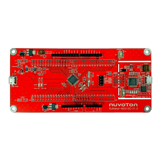
NuMaker-M251SD NUMAKER-M251SD OVERVIEW Front View Figure 3-1 Front View of NuMaker-M251SD Figure 3-1 shows the main components and connectors from the front side of NuMaker-M251SD. The following lists components and connectors from the front view: Target Chip: M251SD2AE(U1) ... -
Page 10: Rear View
NuMaker-M251SD Rear View Figure 3-2 shows the main components and connectors from the rear side of NuMaker-M251SD. The following lists components and connectors from the rear view: Nu-Link2-Me MCUVCC Power Switch (ICEJPR1) ICEVCC Power Switch (ICEJPR2) ICEVCC Power Switch... -
Page 11: Extension Connectors
Table 3-1 Extension Connectors 3.3.1 Pin Assignment for Extension Connectors The NuMaker-M251SD provides the M251SD2AE target chip onboard and full pins extension connectors (JP3, JP4, JP5 and JP6). The Figure 3-3 shows the M251SD2AE extension connectors. Pin17 ~ Pin32 Pin1 ~ Pin16... - Page 12 NuMaker-M251SD M251SD2AE Header Pin No. Function PB.6/EADC0_CH6/USCI1_DAT1/UART1_RXD/BPWM1_CH5/PWM1_BRAKE1 JP3.1 JP3.2 /PWM1_CH5/INT4/ACMP1_O PB.5/EADC0_CH5/ACMP1_N/I2C0_SCL/USCI_CTL0/SC0_CLK/PWM0_CH0/UART2_T JP3.3 JP3.4 XD/TM0/INT0 PB.4/EADC0_CH4/ACMP1_P1/I2C0_SDA/USCI1_CTL1/SC0_DAT/PWM0_CH1/UART2_ JP3.5 JP3.6 RXD/TM1/INT1 PB.3/EADC0_CH3/ACMP0_N/I2C1_SCL/UART1_TXD/USCI1_DAT1/SC0_RST/PWM0_ JP3.7 JP3.8 CH2/PWM0_BRAKE0/TM2/INT2 PB.2/EADC0_CH2/ACMP0_P1/I2C1_SDA/UART1_RXD/USCI1_DAT0/SC0_PWR/PWM0 JP3.9 JP3.10 _CH3/TM3/INT3 PB.1/EADC0_CH1/UART2_TXD/USCI1_CLK/I2C1_SCL/PWM0_CH4/PWM1_CH4/PWM JP3.11 JP3.12 0_BRAKE0 PB.0/EADC0_CH0/UART2_RXD/SPI0_I2SMCLK/I2C1_SDA/PWM0_CH5/QSPI0_MOSI1 JP3.13 JP3.14 /PWM0_CH5/PWM1_CH5/PWM0_BRAKE1 JP3.15 JP3.16 PA.11/ACMP0_P0/USCI0_CLK/BPWM0_CH0/TM0_EXT JP3.17 JP3.18 PA.10/ACMP1_P0/USCI0_DAT0/BPWM0_CH1/TM1_EXT JP3.19...
-
Page 13: Table 3-2 M251Sd2Ae Full-Pin Extension Connectors And Gpio Function List
NuMaker-M251SD JP4.5 JP4.6 PC.5/QSPI0_MISO1/UART2_TXD/I2C1_SCL/PWM1_CH0/PSIO0_CH0 JP4.7 JP4.8 PC.4/QSPI0_MOSI1/UART2_RXD/I2C1_SDA/PWM1_CH1/PSIO0_CH1 JP4.9 JP4.10 PC.3/QSPI0_SS/UART2_nRTS/I2C0_SMBAL/PWM1_CH2/PSIO0_CH2 JP4.11 JP4.12 PC.2/QSPI0_CLK/UART2_nCTS/I2C0_SMBSUS/PWM1_CH3/PSIO0_CH3 JP4.13 JP4.14 PC.1/QSPI0_MISO0/UART2_TXD/I2C0_SCL/PWM1_CH4/ACMP0_O JP4.15 JP4.16 PC.0/QSPI0_MOSI0/UART2_RXD/I2C0_SDA/PWM1_CH5/ACMP1_O JP4.17 JP4.18 PD.3/USCI0_CTL1/SPI0_SS/USCI1_CTL0/UART0_TXD JP4.19 JP4.20 PD.2/USCI0_DAT1/SPI0_CLK/UART0_RXD JP4.21 JP4.22 PD.1/USCI0_DAT0/SPI0_MISO JP4.23 JP4.24 PD.0/USCI0_CLK/SPI0_MOSI/TM2 JP4.25 JP4.26 PA.12/I2C1_SCL/BPWM1_CH2 JP4.27 JP4.28 PA.13/I2C1_SDA/BPWM1_CH3 JP4.29 JP4.30 PA.14/UART0_TXD/BPWM1_CH4 JP4.15... -
Page 14: Arduino Uno Compatible Extension Connectors
NuMaker-M251SD 3.3.2 Arduino UNO Compatible Extension Connectors Figure 3-4 shows the Arduino UNO compatible extension connectors. MOSI PA.10 PB.15 USCI0_DAT0 MISO RESET PA.9 PA.11 nRESET PA.8 USCI0_DAT1 USCI0_CLK UART1_RXD PWM0_CH3 PB.2 PB.1 EADC0_CH1 I2C1_SCL UART2_TXD PB.0 EADC0_CH0 I2C1_SDA UART2_RXD UART1_TXD PWM0_CH2 PB.3... -
Page 15: Table 3-3 Arduino Uno Extension Connectors And M251Sd2Ae Mapping Gpio List
NuMaker-M251SD NuMaker-M251SD NuMaker-M251SD Header Header Compatible to Compatible to GPIO Pin of M251 GPIO Pin of M251 Arduino UNO Arduino UNO NU3.1 PB.2 NU2.6 PB.1 NU3.2 PB.3 NU2.5 PB.0 NU3.3 PC.4 NU2.4 PB.4 NU3.4 PC.5 NU2.3 PB.5 NU3.5 PC.3 NU2.2 PB.6... -
Page 16: System Configuration
NuMaker-M251SD System Configuration The NuMaker-M251SD is able to adopt multiple power supply. External power source includes NU1 Vin (7 V to 12 V), VDD (depends on target chip operating voltage), and PC through USB connector. By using switches and voltage regulator, multiple power domains can be created on the NuMaker- M251KG. -
Page 17: Power Sources
Table 3-9 presents the USB connectors. Connector Comment ICE USB connector on Nu-Link2-Me for power supply, debugging and ICEJ3 programming from PC. USB PWR connector on NuMaker-M251SD for power supply. Table 3-9 USB Connectors 3.4.7 Power Switches Table 3-10 presents the power switches. Switch... -
Page 18: Power Supply Models
NuMaker-M251SD 3.4.8 Power Supply Models External Power Supply through Nu-Link2-Me to Target Chip The external power supply source on Nu-Link2-Me is shown in Figure 3-5. Figure 3-5 External Power Supply Sources on Nu-Link2-Me To use ICEJ3 as external power supply source with Nu-Link2-Me, please follow the below steps: 1. -
Page 19: Figure 3-6 External Power Supply Sources On M251 Platform
2. Separate the Nu-Link2-Me from NuMaker-M251SD. 3. Connect the external power supply to Vin or J2. To use JP1 as external power supply source with Nu-Link2-Me separated from NuMaker-M251SD, please follow the below steps: 1. Switch the SW2 to OFF. -
Page 20: Figure 3-7 Separate The Nu-Link2-Me From Numaker-M251Sd
Connector " (JP2) Separate Nu-Link2-Me NU1 pin8 (Vin) Figure 3-7 Separate the Nu-Link2-Me from NuMaker-M251SD Table 3-12 presents all power models when supplies external power through M251 platform. The M251 platform external power sources are highlighted in yellow. ICEJPR1 ICEJPR2... -
Page 21: External Reference Voltage Connector
NuMaker-M251SD External Reference Voltage Connector Table 3-13 presents the external reference voltage connector. Connector Comment Connector for user to easily connect to the external reference voltage pin VREF1 of the target chip. User needs to remove the L5 ferrite bead. -
Page 22: Extension Connectors
Table 3-17 Push-Buttons LEDs Table 3-18 presents the LEDs. Component Comment Power LED The power LED indicates that the NuMaker-M251SD is powered. PB14 LED The LED is connected to the target chip PB.14. ICES0, ICES1, ICES2 Nu-Link2-Me status LED. and ICES3 Table 3-18 LEDs Aug. -
Page 23: Nu-Link2-Me
NuMaker-M251SD Nu-Link2-Me The Nu-Link2-Me is a debugger and programmer that supports on-line programming and debugging through SWD interface. The on-board 16 Mbit SPI Flash allows it to off-line program the target microcontroller. Additionally, the Nu-Link2-Me provides virtual COM port (VCOM) function to print out messages on PC. -
Page 24: Toolchains Supporting
KEIL MDK Nuvoton edition M0/M23 IAR EWARM NuEclipse GCC (for Windows) NuEclipse GCC (for Linux) Nuvoton Nu-Link Driver Installation Download and install the latest Nuvoton Nu-Link Driver. Download and install Nu-Link_Keil_Driver when using Keil MDK. Download and install Nu-Link_IAR_Driver when using IAR EWARM. -
Page 25: Figure 3-10 Nu-Link Usb Driver Installation
NuMaker-M251SD Figure 3-10 Nu-Link USB Driver Installation Aug. 18, 2020 Page 25 of 45 Rev 1.00... -
Page 26: Bsp Firmware Download
2. Connect the ICE USB connector shown in Figure 3-12 to the PC USB port through USB cable. Figure 3-12 ICE USB Connector 3. Find the “Nuvoton Virtual COM Port” on the Device Manger as Figure 3-13. Aug. 18, 2020 Page 26 of 45 Rev 1.00... -
Page 27: Figure 3-13 Device Manger
NuMaker-M251SD Figure 3-13 Device Manger 4. Open a serial port terminal, PuTTY for example, to print out debug message. Set the speed to 115200. Figure 3-14 presents the PuTTY session setting. Figure 3-14 PuTTY Session Setting Aug. 18, 2020 Page 27 of 45... -
Page 28: Find The Example Project
NuMaker-M251SD Find the Example Project Use the “Template” project as an example. The project can be found under the BSP folder as shown in Figure 3-15. M251_Series_BSP_CMSIS_V3.XX.XXX SampleCode Template Keil Figure 3-15 Template Project Folder Path Execute the Project under Toolchains Open and execute the project under the toolchain. -
Page 29: Figure 3-17 Project File Migrate To Version 5 Format
Figure 3-17 Project File Migrate to Version 5 Format 2. Make sure the debugger is “Nuvoton Nu-Link Debugger” as shown in Figure 3-18 and Figure 3-19. Note: If the dropdown menu in Figure 3-18 does not contain “Nuvoton Nu-Link Debugger” item,... -
Page 30: Figure 3-19 Programming Setting In Options Window
NuMaker-M251SD Figure 3-19 Programming Setting in Options Window 3. Rebuild all target files. After successfully compile the project, download code to the flash memory. Click “Start/Stop Debug Section” button can enter debug mode. 1. Rebuild 2. Successfully compile 3. Download 4. -
Page 31: Figure 3-21 Keil Mdk Debug Mode
NuMaker-M251SD source code, assembly language, peripherals’ registers, and setting breakpoint, step run, value monitor, etc. 3 1 2 1. Run 2. Stop 3. Reset Figure 3-21 Keil MDK Debug Mode Figure 3-22 Debug Message on Serial Port Terminal Windows Aug. -
Page 32: 3.17.2 Iar Ewarm
NuMaker-M251SD 3.17.2 IAR EWARM This section provides steps to beginners on how to run a project by using IAR EWARM. 1. Double click the “Template.eww” to open the project. 2. Make sure the toolbar contain “Nu-Link” item as shown in Figure 3-23. -
Page 33: 3.17.3 Nueclipse
NuMaker-M251SD 4. Figure 3-25 shows the debug mode under IAR EWARN. Click “Go” and the debug message will be printed out as shown in Figure 3-26. User can debug the project under debug mode by checking source code, assembly language, peripherals’ registers, and setting breakpoint, step run, value monitor, etc. -
Page 34: Figure 3-27 Import The Project In Nueclipse
NuMaker-M251SD Figure 3-27 Import the Project in NuEclipse M251_252_Series_BSP_CMSIS_V3.XX.XXX\SampleCod e\Templ M251_252__Series_BSP_CMSIS_V3.XX.XXX\SampleCode\Te mplate\G Figure 3-28 Import Projects Windows 3. Click the “Template” project and find the project properties as shown in Figure 3-29. Make sure the settings are the same as settings in Figure 3-30. -
Page 35: Figure 3-29 Open Project Properties Window
NuMaker-M251SD Figure 3-29 Open Project Properties Window Figure 3-30 Project Properties Settings 4. Click the “Template” project and build the project. Aug. 18, 2020 Page 35 of 45 Rev 1.00... -
Page 36: Figure 3-31 Build Project
NuMaker-M251SD Figure 3-31 Build Project 5. After the project is built, click the “Template” project and set the “Debug Configuration” as shown in Figure 3-32. Follow the settings presented in Figure 3-33, Figure 3-34 and Figure 3-35 to enter debug mode. -
Page 37: Figure 3-33 Main Tab Configuration
NuMaker-M251SD Note 1: Double click the “GDB Nuvoton Nu-Link Debugging” to create the subitem. Note 2: After the project is built, the “*.elf” file will be shown in “C/C++ Application” frame. Figure 3-33 Main Tab Configuration Figure 3-34 Debugger Tab Configuration Aug. -
Page 38: Figure 3-35 Startup Tab Configuration
NuMaker-M251SD Note 1: User must follow those settings highlighted in green, and can configure other settings depend on the needs. Figure 3-35 Startup Tab Configuration Aug. 18, 2020 Page 38 of 45 Rev 1.00... -
Page 39: Figure 3-36 Nueclipse Debug Mode
NuMaker-M251SD 6. Figure 3-36 shows the debug mode under NuEclipse. Click “Resume” and the debug message will be printed out as shown in Figure 3-37. User can debug the project under debug mode by checking source code, assembly language, peripherals’ registers, and setting breakpoint, step run, value monitor, etc. -
Page 40: Numaker-M251Sd Schematics
NuMaker-M251SD NUMAKER-M251SD SCHEMATICS Nu-Link2-Me Figure 4-1 shows the Nu-Link2-Me circuit. The Nu-Link2-Me is a debugger and programmer that supports on-line programming and debugging through SWD interface. 3.3V ICER1 O f f - page C onnect or 200 1% USB_HS_CAP R0603... -
Page 41: M251 Platform
NuMaker-M251SD M251 platform Figure 4-2 shows the M251 platform circuit. P1 - P16 P33 - P48 PF0_ICE_DAT PB6_NU2_A1 TICEDAT PF1_ICE_CLK PB5_NU2_A2 TICECLK PB4_NU2_A3 PC5_NU3_D3 PB3_NU3_D1/TX PC4_NU3_D2 PB2_NU3_D0/RX PC3_NU3_D4 PB1_NU2_A5/SCL/TX PC2_NU3_D5 PB0_NU2_A4/SDA/RX PC1_NU4_SCL PA11_NU5_CLK PC0_NU4_SDA PA10_NU5_MOSI PA9_NU5_MISO PA8_NU5_SS PF14 PA12 nRESET... -
Page 42: Extension Connector
NuMaker-M251SD Extension Connector Figure 4-3 shows extension connectors of NuMaker-M251SD. P1 - P16 P33 - P48 PB6_NU2_A1 TICEDAT PB5_NU2_A2 TICECLK PC1_NU4_SCL I2C_SCL PB4_NU2_A3 PC5_NU3_D3 PC0_NU4_SDA I2C_SDA PB3_NU3_D1/TX PC4_NU3_D2 VREF VREF PB2_NU3_D0/RX PC3_NU3_D4 PB1_NU2_A5/SCL/TX PC2_NU3_D5 TICERST PA2_NU3_D13/CLK MCU_RESET PB0_NU2_A4/SDA/RX PC1_NU4_SCL NU1_3VCC... -
Page 43: Pcb Placement
NuMaker-M251SD PCB Placement Figure 4-4 and Figure 4-5 show the front and rear placement of NuMaker-M251SD. Figure 4-4 Front Placement Figure 4-5 Rear Placement Aug. 18, 2020 Page 43 of 45 Rev 1.00... -
Page 44: Revision History
NuMaker-M251SD REVISION HISTORY Date Revision Description 2020.08.18 1.00 Initially issued. Aug. 18, 2020 Page 44 of 45 Rev 1.00... - Page 45 NuMaker-M251SD Important Notice Nuvoton Products are neither intended nor warranted for usage in systems or equipment, any malfunction or failure of which may cause loss of human life, bodily injury or severe property damage. Such applications are deemed, “Insecure Usage”.
Need help?
Do you have a question about the NuMaker-M251SD and is the answer not in the manual?
Questions and answers