Advertisement
Quick Links
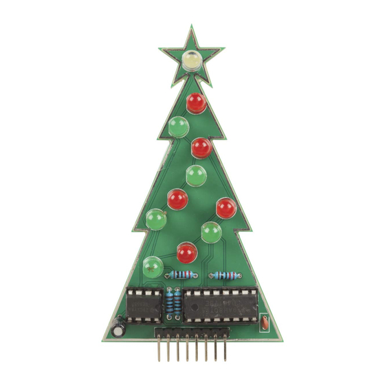
XC3754 Soldering Guide
Kit Contents
Open up the package and lay out the contents to ensure you have them all. You should
have:
5 Green and 5 Red LEDs
1 Clear LED
4 Resistors (2×220Ω, 1×1kΩ, 1×10kΩ)
2 Capacitors (one ceramic, one electrolytic)
2 ICs (integrated circuits, or "chips"): 555 & 4017, and matching sockets
Header pins, Header cable
PCB board.
Preparing the LEDs
Start by placing one of the LEDs in the circular pads marked out on the PCB board. You
will notice that the circular markings (called the silkscreen) have a flat section, this marks
the negative lead of the LED. You will be able to feel a similar flat section on the base of
the LED with your fingers. You can also notice that one of the LED legs is longer than
the other, which marks the positive.
Page 1 of 10
Advertisement

Related Manuals for Jaycar Duinotech Build A Christmas Tree


Summary of Contents for Jaycar Duinotech Build A Christmas Tree
- Page 1 XC3754 Soldering Guide Kit Contents Open up the package and lay out the contents to ensure you have them all. You should have: 5 Green and 5 Red LEDs 1 Clear LED 4 Resistors (2×220Ω, 1×1kΩ, 1×10kΩ) ...
- Page 2 XC3754 Soldering Guide Place the LED into the marked section so that the longer lead is in the hole away from the flat marked section. Then bend the legs of the LED so that the legs hold the LED into place and it can’t drop out or wiggle around too much.
- Page 3 XC3754 Soldering Guide When preparing the iron, and it is sufficiently hot enough to melt solder, you want to touch the solder onto the iron itself, so that the solder and flux (a component of the solder responsible for keeping the joint clean and flowy) cleans any rust or dirt off the tip of the iron.
- Page 4 XC3754 Soldering Guide How to solder correctly One of the main important notes about soldering is the need for the components to be the correct temperature for the solder to bind to them, in this case it is both the PCB pads and the LED legs.
- Page 5 XC3754 Soldering Guide It’s important to make sure that the solder joint is good while you make them, as they can be difficult to track down once you have built the circuit and you’re trying to find a reason it doesn’t work as expected. Below are 3 types of solder joints; what you’re looking for is a nice “volcano”...
- Page 6 XC3754 Soldering Guide Soldering the resistors You will find 4 resistors in this kit, 2 of them are together on the same tag (220 ohms) which correspond to R3 and R4 on the PCB board. You can check what value they are by the resistor colour codes: for 220 ohms, you should find red-red-black-black-brown, which is a 5-band colour code.
- Page 7 XC3754 Soldering Guide We do this as a stress relief for the resistor and is good practice to get in to. Bending it before placing it into the PCB means that the joint will not be under stress once it is soldered in.
- Page 8 XC3754 Soldering Guide For the other two resistors, your band-colour recognition is put to the test, (don’t worry, you can use a multimeter or an online calculator to check if you are not sure). For R1 you want to use the 10kΩ resistor, which should be: brown-black-black-red-brown = 1 0 0, ×100, 1% tolerance.
- Page 9 XC3754 Soldering Guide This should be an easy soldering job, as the flat tabs of the IC sockets absorb heat very well, so try to rotate the project so the iron comes from the top of the board and touches the entire pad and socket tab at the same time.
- Page 10 XC3754 Soldering Guide The header pins fit on the PCB board with the short side of the plastic going through the PCB holes, and the longer legs are on the same side as every other component. Here, we’ll hold it from the left, and solder the right most connection, just to hold it in place.
Need help?
Do you have a question about the Duinotech Build A Christmas Tree and is the answer not in the manual?
Questions and answers