Advertisement
Quick Links
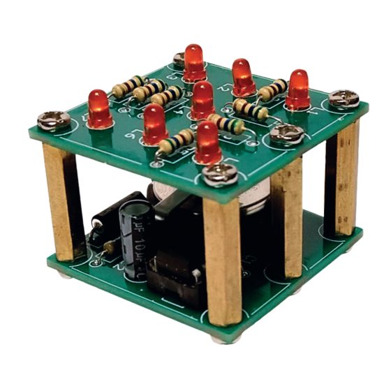
Thank you for purchasing the Electronic Dice Kit
Take your soldering skills to the next level with this Electronic
Dice Kit.
Once built, you simply shake the module to generate a
random number between one a six, indicated by the LEDs
on the top!
Powered by a CR2032 battery (not included).
If this is the first time you are getting into electronics and
handling a soldering iron, please download our Soldering
Guide from our website.
Build Instructions &
Soldering Guide available at:
www.jaycar.com.au/p/KM1099
RECOMMENDED TOOLS. You will need the usual Maker essentials, including a soldering iron (TS1652 Soldering Iron Kit),
solder (NS3010), and side cutters (TH1897). A third-hand PCB holder (TH1987) is also recommended to make soldering easier.
Disclaimer: Content can change without prior notice. Please visit the website page for the most up-to-date information.
learn to solder: Electronic Dice Kit
learn to solder:
Electronic
Dice Kit
A GOOD SOLDER JOINT
The diagram here shows you a good solder joint and two
bad solder joints. A good solder joint is clean and shiny with
a "volcano" shape, which means the component's leg is fully
soldered to the entire solder pad on the circuit board. If your
solder joint is like the one shown in the middle, it means
you have not applied enough heat to the solder pad on the
circuit board. If your solder joint looks like the one on the
right, it means the component leg was not heated enough
by your soldering iron for the solder to join properly.
GOOD
Shiny "Volcano"
The solder pad is
type shape
too cold
Cat no.
KM1099
BAD
BAD
Component leg
too cold
1
Advertisement

Related Manuals for Jaycar Maycar Electronic Dice Kit


Summary of Contents for Jaycar Maycar Electronic Dice Kit
- Page 1 Build Instructions & Soldering Guide available at: www.jaycar.com.au/p/KM1099 RECOMMENDED TOOLS. You will need the usual Maker essentials, including a soldering iron (TS1652 Soldering Iron Kit), solder (NS3010), and side cutters (TH1897). A third-hand PCB holder (TH1987) is also recommended to make soldering easier.
- Page 2 Kit contents: PRODUCT PCB MARKING / COMMENT Circuit Board Top L1-L7 markings is the top board Circuit Board Bottom E1 marking is the bottom board 1MΩ Resistor (Brown-Black-Green-Gold) 560Ω Resistor (Green-Blue-Brown-Gold) R1 - R7 Red LEDs L1 to L7 12F508-I/P IC U1 ( Align with the notch ) IC Socket For the 12F508-I/P IC...
Need help?
Do you have a question about the Maycar Electronic Dice Kit and is the answer not in the manual?
Questions and answers