Table of Contents
Advertisement
Quick Links
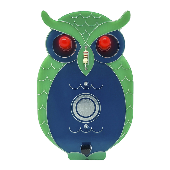
Thank you for purchasing the Owl Badge Kit.
Here's a great way to get started with soldering, learn
a little about electronics, and end up with a really fun
wearable badge at the end!
This kit is part of a range of wearable badges designed
exclusively by Jaycar. Each project is powered by a
small CR2032 Lithium coin battery (Not included. We
recommend, SB2522), and the badges include a lapel
pin so you can wear it too.
Each of the designs has a different look and feel, while
the electronics involved is slightly different in each one,
so you'll learn more about electronics and how it works
even if you build them all!
Kit contents:
QTY
CAT. NUMBER PRODUCT
1
Circuit Board
1
Lapel Pin
ZD0150
2
5mm Red LEDs
1
PH9238
CR2032 Battery Holder
1
RR0556
220Ω Resistor (Red-Red-Brown-Gold)
1
ZT2298
2N2222 Transistor
ADDITIONAL PARTS REQUIRED (Not included)
1
SB2522
CR2032 Battery
Disclaimer: Content can change without prior notice. Please visit the website page for the most up-to-date information.
learn to solder: Owl Badge Kit
learn to solder:
Badge Kit
WITH TOUCH-ACTIVATED LED EYES
Before you start:
Before you start building your project, open up the package
and lay out the contents to ensure you have them all based
on the parts list.
You should also prepare a clean workspace and get all of the
tools needed, which we will discuss on the next page.
PCB MARKING
-
-
Cat no.
KM1092
Owl
1
Advertisement
Table of Contents

Summary of Contents for Jaycar Maycar Owl Badge Kit
- Page 1 This kit is part of a range of wearable badges designed exclusively by Jaycar. Each project is powered by a small CR2032 Lithium coin battery (Not included. We recommend, SB2522), and the badges include a lapel pin so you can wear it too.
- Page 2 Note: Make sure you’re holding the lead as you’re cutting as the Jaycar stocks a wide range of solder should you run out. For cut lead can fly off when trimming causing an eye injury.
- Page 3 Construction: STEP 3: LEDS Cathode Anode LEDs only work in one direction. The long leg is positive (+), Front View Rear View and the short leg and side with the flat edge on the LED’s body is the negative (-) side. Insert both LEDs into the front STEP 1: RESISTORS side of the circuit board so that the flat edge on the LED matches what is printed on the circuit board.
- Page 4 Testing & troubleshooting: DOUBLE-CHECK TROUBLESHOOTING GUIDE If your badge doesn’t work: Before you apply power, it is good practice to double- check that you have the 1. Make sure your battery is not flat. Try using a fresh battery. components in the right spot and soldered correctly.


Need help?
Do you have a question about the Maycar Owl Badge Kit and is the answer not in the manual?
Questions and answers