
Related Manuals for PowerTech MP3755


Summary of Contents for PowerTech MP3755
- Page 1 12V/24V 30A PWM Solar Charge Controller for Lithium or SLA Batteries MP3755 User Manual...
- Page 2 Contents Product Over: Page 3 Product Appearance Diagram: Page 4 LCD Diagram: Pages 5‐8 Product Function Settings and LCD Diagram: Pages 9‐14 Product Specifications: Pages 15‐18 Certification and Environmental Protection: Page 19 Precautions: Page 19 ...
- Page 3 1. Product Overview This product adopts the latest PWM control technology and intelligent solar controller controlled by MCU. It integrates WIFI function and allows viewing the working status of the product through mobile APP, featuring high efficiency, low loss, small size, light weight, LCD interface, backlight, and complete protection functions. It is the best choice for charging onboard, domestic and industrial batteries. The product has the following features. 1. Allow charging 12V/24V lead‐acid battery and lithium battery, which is more ...
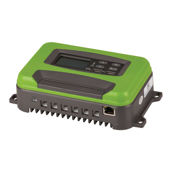
- Page 4 2. Product Appearance Diagram Product Appearance Diagram Fig. 1: Structure Diagram A: Solar input connected to the positive electrode, B: Solar input connected to the negative electrode C: Battery connected to positive electrode, D: Battery connected to negative electrode E: Load output positive, F: Load output negative; E. MODE button H: LED indicator light, red light on in case of error, flashing green during charging, stay green after fully charged.
- Page 6 To view LCD parameters and set functions, press the UP/DOWN button in the default interface (battery voltage interface) to view the battery charging current; press the Menu button once, then press the UP/DOWN button to view the battery in turn to view the battery voltage, charging current, load current, solar voltage, time, and LCD display as follows.
- Page 7 Press the Menu button twice in the default interface to view the solar panel voltage and current, and press the UP/DOWN button to switch. ...
- Page 8 Press the Menu button once in the default interface to view the load voltage and current, and press the UP/DOWN button to switch. ...
- Page 9 Press the Menu button three times in the default interface to view the time. ...
- Page 10 Function settings and LCD icons are as follows: Press and hold Menu for 2 seconds in the default state to enter the Settings interface, press the Menu button repeatedly to switch to battery category setting, WIFI switch setting, undervoltage protection setting, restart voltage setting after undervoltage, clock setting, timer switch setting, dawn load TO mode, and dawn load Ld mode. Press the “OK” button to enter desired function, press the UP/DOWN button to select, and then press “OK” to confirm. Battery category mode Above is the AGM battery mode. ...
- Page 11 Above is the lithium battery mode Above is the STD battery mode ...
- Page 12 Above is the WIFI switch control mode Above is the battery undervoltage protection setting ...
- Page 13 The figure above shows the restart voltage setting after undervoltage ...
- Page 14 The figure above shows the time setting The figure above shows the LO timer load mode setting. When the PV is less than 11V, the clock 1 is the delay on load, and the clock 2 is the delay off load time (in minutes) when the PV is greater than 11V.
- Page 15 The figure above shows the Ld load mode setting. When the PV is less than 11V, the clock 1 is turned on, the clock 2 is the off load time, and then the load is turned on until the PV is greater than the 11V off load. The “TO”, “LO”...
- Page 16 5. Product Function 5.1 This product adopts 4-stage charging mode: battery test; current limiting; constant voltage; float charging. 5.2 Battery test: After the battery is connected, it will check whether the battery meets the voltage requirements for the operation of this product. 5.3 Current limiting: This product allows a maximum charging current of 30A.
- Page 17 reached, the product will be charged at the highest voltage point until the current is reduced to below 3A or the time exceeds 3 hours. 5.5 Float charging: Float charging is started after constant voltage charging, but charging voltage and current are smaller; it is maintenance charging and allows a longer time of safe charging.
- Page 18 5.8 Technical Specifica ons 6. Cer fica and environmental prot Meet CE, RoHs and PAHs requirements; 7. Prec 7.1 The solar input voltage must not exceed 51V (VOC), and the current must not exceed 30A. 7.2 Pay a en on to polarity when co g, and do not reverse the polarity.
Need help?
Do you have a question about the MP3755 and is the answer not in the manual?
Questions and answers
How do I enable mppt? My solar charge controller shows it at startup but is currently disabled. It is also shown in the manual
You cannot enable MPPT on the PowerTech MP3755 solar charge controller because it uses PWM (Pulse Width Modulation) technology, not MPPT (Maximum Power Point Tracking).
This answer is automatically generated
@Mr. Anderson ok thanks (: But how do I enable wifi? I have the exact same model as in the manual but the wifi option in setting isn’t there on my regulator.