Advertisement
Quick Links
Overview
RGBHV (BNC) DAD (Distribution Amplifier Driver) Modules have either one input and
four outputs for a 1:4 distribution or one input and six outputs for a 1:6 distribution of
RGBHV analog signals. The single RGBHV input is distributed to four or six outputs
over standard cable runs of up to 250 ft. (76.2 m) with no additional equipment
required. Each output can be independently adjusted for gain and peaking to ensure
the proper amount of compensation is provided for each cable run. This guide contains
complete information for this product.
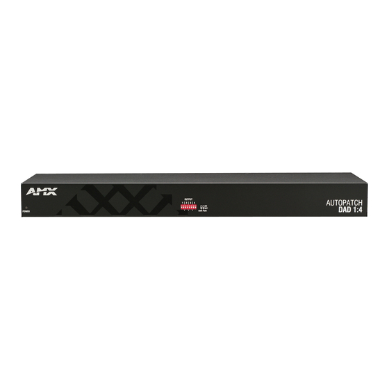
FIG. 1
RGBHV (BNC) DAD 1:4 model FG1052-13
FIG. 2
RGBHV (BNC) DAD 1:6 model FG1052-16
Product Specifications
General Specifications
Approvals
Pending
AC Power
100 to 240 VAC single phase, 50-60 Hz
Consumption (max.)
120 VAC, 650 mA
Consumption (typical)
120 VAC, 100 mA
Operational Temperature
32° to 110° F (0° to 43° C)
Humidity
0 to 90% non-condensing
Dimensions
5.15 in. (13.08 cm) depth
17.40 in. (44.20 cm) width without rack ears
19.00 in. (48.26 cm) width with rack ears
1.72 in. (4.37 cm) 1 RU height without feet
Weight: Approx. 4.5 lbs. (2 kg)
Connector Type
BNC
RGBHV Signal Specifications
Frequency Response
Signal to Noise Ratio
Vin = 0.7 V, 100% IRE
Level
Input (max.)
Output (max.)
Impedance
Input
Output
Return Loss
Sync Level
Input (max.)
Output (max.)
Sync Impedance
Input
Output
AutoPatch RGBHV (BNC) DAD Modules
±3 dB, 450 MHz or better
>65 dB
±1.75 V
±1.75 V
75 ohms
75 ohms
-45 dB @ 5 MHz
0 V to +5 V
0 V to +5 V
510 ohms
50 ohms
Gain & Peaking* Specifications
Gain
OFF
Unity
ON
+0.85 dB
Peaking
OFF
No peaking
ON
8 dB @ 150 MHz
8 dB @ 300 MHz
Cable Length (max.)
250 ft. (76.2 m)
* Gain and peaking are independent switches that allow the user to turn on or off the
gain and peaking.
Installation
Mounting Options
– Attach the rubber feet (included) to the bottom of the module.
Desktop
Rack Mounting
To rack mount a module:
1.
Remove one screw from each side of the module as shown in FIG. 3. Do not
reuse screw for rack ear.
2.
Attach rack ears as shown in FIG. 3 (screws provided).
Remove screw
FIG. 3
Remove screw and attach rack ears
3.
Place the module in a standard EIA 19 in. (48.26 cm) rack and secure it to the
rack with screws.
Typical Setup
1:4 DAD Module
Source Device
FIG. 4
Typical system setup using 1:4 DAD
Attaching Cables
To attach connectors:
1.
Fasten the BNC connectors from the source and destination devices onto the
BNC connectors on the module (FIG. 5).
2.
Attach the power cord into the power receptacle on the module and into an
external AC power source.
From
source
Power
FIG. 5
Attach input and output connectors (1:6 model shown)
3.
Press the "I" side of the power switch.
4.
Apply power to the source and destination devices.
Note: The power indicator LED is on the module's front.
Quick Start Guide
Destination Devices
To destinations
BNCs
BNCs
Advertisement

Related Manuals for AMX FG1052-13


Summary of Contents for AMX FG1052-13
- Page 1 Each output can be independently adjusted for gain and peaking to ensure the proper amount of compensation is provided for each cable run. This guide contains complete information for this product. FIG. 1 RGBHV (BNC) DAD 1:4 model FG1052-13 FIG. 2 RGBHV (BNC) DAD 1:6 model FG1052-16 Product Specifications...
- Page 2 ©2007 AMX. All rights reserved. AMX and the AMX logo are registered trademarks of AMX. AMX reserves the right to alter specifications without notice at any time. 3000 RESEARCH DRIVE, RICHARDSON, TX 75082 • 800.222.0193 • fax 469.624.7153 • technical support 800.932.6993 • www.amx.com Result...
Need help?
Do you have a question about the FG1052-13 and is the answer not in the manual?
Questions and answers