Advertisement
Quick Links
Advertisement

Related Manuals for Samoa LARIUS Miro Liner Plus


Summary of Contents for Samoa LARIUS Miro Liner Plus
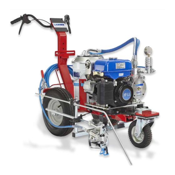
- Page 1 w w w . l a r i u s . c o m Mirò Liner PLus Professional airless diaphragm road marking machines...
- Page 3 Larius the ideal choice for achieving professional performance. WELL PROVEN TECHNICAL QUALITY FOR ANY ON-GROUND MARKING APPLICATION The LARIUS airless line markers successfully join product performan- ce with operator requirements and allow the marking and the mainte- nance of any kind of pavement lines on roads, motorways, airports, pedestrian crossings, cycle paths, yards and wherever is required by the Highway Code with regards to horizontal road signs, guaranteeing perfect lines on different surfaces.
- Page 4 Professional line markers for the ideal “line” WHERE’S TARMAC... We can make a long “Road” together MIRò LINER PLUS DALì LINER PLUS GIOTTO LINER PLUS VIKING HAND PUSH HAND PUSH SELF-PROPELLED LINER Motor Power 5,5 - HP 5,5 - HP 10 - HP 12,75 - HP Max.
- Page 5 Professional line markers for the ideal “line” ... THERE’S LARIUS An already marked work when you start. EXCALIBUR LINER ZEUS LINER DRAGON LINER EVEREST TH K2 ECO HAND PUSH HAND PUSH SELF-PROPELLED SELF-PROPELLED SELF-PROPELLED 7 - HP 9 - HP 9,5 - HP 14 - HP BATTERIA...
- Page 6 This manual is to be considered as an English language translation of the original manual in Italian. The manufacturer shall bear no responsibility for any damages or inconveniences that may arise due to the incorrect translation of the instructions contained within the original manual in Italian. Due to a constant product improvement programme, the factory reserves the right to modify technical details mentioned in this manual without prior notice.
- Page 7 MIRO’ LINER PLUS MirO’ Liner PLus Professional airless diaphragm road marking machines INDEX Daily .................p.18 INTRODUCTION ............p.2 Periodically ..............p.18 WORKING PRINCIPLE ..........p.3 ROUTINE MAINTENANCE ..........p.18 TECHNICAL DATA ............p.4 Control oil level in the motor ........p.18 DESCRIPTION OF THE EQUIPMENT ......p.7 Top up hydraulic oil ..........p.19 TRANSPORT AND UNPACKING ........p.10 Release the suction valve .........p.19...
- Page 8 MIRO’ LINER PLUS WARNINGS The table below provides the meaning of the symbols used in this manual in relation to using, earthing, operating, maintaining, and repairing of this equipment. Read this operator’s manual carefully before using the equipment. An improper use of this machine can cause injuries to people or things. Do not use this machine when under the influence of drugs or alcohol.
- Page 9 MIRO’ LINER PLUS WORKING PRINCIPLE Airless line-marking guarantees: • Decreased Environmental Impact; MIRÓ LINER PLUS unit is defined line striper with diaphragm pump • Decreased drying time. An electric diaphragm pump is used for high pressure paint spraying without air (known as “airless”). The paint dries quickly and the line is defined in a uniform manner This unit is powered by a petrol engine.
- Page 10 MIRO’ LINER PLUS TECHNICAL DATA 50L tank 20L tank www.larius.com ED. 05 - 08/2020 - Cod. 150162...
- Page 11 MIRO’ LINER PLUS MIRÓ LINER PLUS Internal combustion engine power 5,5 HP 2 l/min Max. Delivery Max. pressure 210 bar Airless spray-gun AT 250 Size of nozzles 11x40 - 13x40 - 15x40 Tank 20l / 50l Colors Manual line-marking series Applications Small jobs of line marking and road maintenance Multi-use sprayer...
- Page 12 MIRO’ LINER PLUS Standard equipment Accessories N° 1 Filter with pressure gauge Rif.18359 Single gun bead dispenser kit N° 1 Diameter of antipulsation tube Ø 3/8” mt.10 Rif.18354 N° 1 Diaphragm stroke compensator Twin gun bead dispenser kit N° 1 Manual airless spray-gun AT250 Rif.4307 N°...
- Page 13 MIRO’ LINER PLUS DESCRIPTION OF THE EQUIPMENT POS. Description Description POS. Product filter Oil discharging cap Pressure valve Oil filter Hydraulic oil filling cap Pressure gauge Pumping unit Oil level liht www.larius.com ED. 05 - 08/2020 - Cod. 150162...
- Page 14 MIRO’ LINER PLUS POS. POS. Description Description lt. 20 tank Start-up cord Gun operating lever Cold start-up lever Directional wheel lock/release lever Fuel tap Fuel tank Air filter Accelerator Pivoting wheel www.larius.com ED. 05 - 08/2020 - Cod. 150162...
- Page 15 MIRO’ LINER PLUS POS. Description POS. Description Recirculation tube AT 250 gun Product feeding tube Spraying gun feeding tube Color unit Brake Recirculation valve www.larius.com ED. 05 - 08/2020 - Cod. 150162...
- Page 16 MIRO’ LINER PLUS TRANSPORT Read carefully and entirely the following instruc- tions before using the product. Please save these AND UNPACKING instructions in a safe place. • The packed parts should be handled as indicated in the The unauthorised tampering/replacement of one symbols and markings on the outside of the packing.
- Page 17 MIRO’ LINER PLUS Engine safety precautions: The high speed of the product in the hose can create • Read the engine operator’s manual annex. static electricity through discharges and sparks. It is suggested to earth the equipment. The pump is earthed through the earth cable of the supply.
- Page 18 MIRO’ LINER PLUS GUN CONNECTION STARTING THE MOTOR In order to start the motor, proceed as follows: • Connect the flexible tube (F5) to the connector (F6) and the gun (F7) ensuring to tighten the fittings (the use of two • Fill the fuel tank (F8).
- Page 19 MIRO’ LINER PLUS • Turn the equipment’s switch (F11) to ON (I) • Fill the product tank with wash fluid. • Clean the inside of the tank with a brush. • Bring the accelerator lever (F12) to about 1/2 of its run. •...
- Page 20 MIRO’ LINER PLUS • Open the recirculating-safety valve (F16). • Once the wash fluid has circulating enough, close the recirculating-safety valve (F16). OPEN CLOSE • Start the motor following the indications provided in the • Remove the gun (F14) from its support and point it into a chapter “STARTING THE MOTOR”.
- Page 21 MIRO’ LINER PLUS • When the pump idles stop the combustion engine. • At this point the machine is ready. If water-based paints are to be used, after the wash with solvent wash the tank again with soap and water, then rinse with clean water (repeating the previously described procedures).
- Page 22 MIRO’ LINER PLUS • Start the motor following the indications provided in the ADJUSTING BELT TENSION chapter “STARTING THE MOTOR”. To adjust the belt tension (G7) you need to follow the following procedure: • Make sure that the re-circulation/safety valve (H3) is closed (spray enabled). • Unscrew the 4 screws (G8). • Unscrew the locknut (G9).
- Page 23 MIRO’ LINER PLUS PAINTING OPERATIONES CLEANING AT THE END OF WORK After having performed all of the operations in the “OPERATION” • Reduce pressure to the minimum (turn counterclockwise the chapter, work may be started using the following controls: pressure control knob (J1) ). • Slowly turn clockwise the pressure control knob (I1) to reach the pressure value in order to ensure a good atomization of the product.
- Page 24 MIRO’ LINER PLUS • Turn the pressure adjustment (J1) handle slightly clockwise • In case of long storage, we recommend you to suck and to make the machine function at minimum pressure (pump to leave light mineral oil inside the pumping group and the activated), until the tank has been completely emptied then flexible hose.
- Page 25 MIRO’ LINER PLUS TOP UP HYDRAULIC OIL CLEANING THE COMPRESSION VALVE With each start up, check the hydraulic oil level by looking through Should the equipment fail to suck the material, remove the the gauge (L1) on the side of the hydraulic body. If necessary, compression valve (L3), clean it with specific solvents according use to top up the level: to the type of paint to be used.
- Page 26 MIRO’ LINER PLUS Check that the ball seals in its seating as follows: • If the quantity of solvent a few minutes later is still identical to that added previously, the ball’s seal in its seating is ensured; • Turn the valve (L3) upside down; • If the solvent flows out the holes at the bottom within a few minutes, replace this valve with a new one; • Put solvent into the groove in the ball’s seating;...
- Page 27 MIRO’ LINER PLUS REPLACING HYDRAULIC OIL After operating for 100 hours, replace the oil in the pump; • Discharge the waste oil through the plug (L4) fitted at the bottom of the pump casing. • Clean the seals on the cap and replace it if worn. Hydraulic oil • Clean the filter (L6). “AGIP OSO 46” • Clean and, if necessary, replace the worn seals (L6). • Fill the pump with the recommended oil until it reaches the maximum level (L5).
- Page 28 MIRO’ LINER PLUS CORRECT PROCEDURE OF DECOMPRESSION • Point the gun (M4) at the receptacle (M5) used to collect the Press the switch (M1) to the OFF position (0) to stop the • product and press the trigger to release the pressure. When equipment.
- Page 29 MIRO’ LINER PLUS PROBLEMS AND SOLUTIONS Problem Solution Cause • Open the petrol manifold; • The equipment does not start • The petrol manifold is closed; • Refill gas tank; • Engine is out of gas; • Use choke; • Cold engine; • Verify and replace it, if necessary; • Setting valve faulty pressure; • Open the drain valve to release • The product is solidified inside the pressure in the circuit and stop the pump;...
- Page 30 MIRO’ LINER PLUS SPARE PARTS Complete frame Rif. 4874 50L Tank RIF.4895 Complete steering unit pag. 37 pag. 35 Rif. 4876 pag. 39 20L Tank RIF.4890 pag. 36 Filter group RIF. 16200 pag. 31 Hydraulic body RIF. 18306 High pressure air gun Transmission unit and po- Accessories pag.
- Page 31 MIRO’ LINER PLUS HYDRAULIC BODY RIF. 18306 WARNING: Always indicate code and quantity for each part required. Pos. Code Description Pos. Code Description 81010 32024 Washer 37406 Screw 18198 Screw 34009 Washer 18324 Spacer 95062 Screw 96031 Screw 18323 Spacer 95153 Washer 18347...
- Page 32 MIRO’ LINER PLUS www.larius.com ED. 05 - 08/2020 - Cod. 150162...
- Page 33 MIRO’ LINER PLUS Pos. Code Description Pos. Code Description 34020 Rivet 21538 Handwheel 21694 Motor technical data label 21540 Bearing 32006 Oil cap 21537 Washer 21526 Hydraulic body 21556 Screw 52015 Cylinder liner 21541 Elastic ring 52016 Membrane Spacer 21559 Bearing 53002 Membrane Assembly...
- Page 34 MIRO’ LINER PLUS Pos. Code Description Pos. Code Description 21635 Colour body 21590 Intake valve assembly 95284 21549 Union Valve body 53001 Diaphragm spacer 53004/6 Lock ring 33026 Seal 53004/5 Spring 21633 OR 3062 53004/4 Guide 21632 53004/2 Ring BK 3062 Spear valve seat 21613 Valve assembly for material...
- Page 35 MIRO’ LINER PLUS FILTER GROUP REF. 16200 WARNING: Always indicate code and quantity for each part required. Pos. Code Description Q.tà Pos. Code Description Q.tà 33008 Manometer 0-400 bar 96203 Gasket 16201 Filter tank 96204 Filter Base 96020 Spring 96026 Union 16205 Standard sieve 60...
- Page 36 MIRO’ LINER PLUS TRANSMISSION UNIT AND POSITIONING RIF. 18358 WARNING: Always indicate code and quantity for each part required. Pos. Code Description Q.tà Pos. Code Description Q.tà 18185 Motor 32024 Washer 18325 Spacer 6151 Nut auto b. 4244M 3637 Washer 18318 Pulleya 18311...
- Page 37 MIRO’ LINER PLUS HIGH PRESSURE GUN AT 250 WARNING: Always indicate code and quantity for each part required. Components Pos. 5 - 11023 - Linkage 11005/3 Ball 11204/1 Ball housing 11205/2 Spring 11205/4 Linkage 11205/5 Sleeve 11205/6 Ring sleeve 11205/7 Bushing Pos.
- Page 38 MIRO’ LINER PLUS COMPLETE 50L TANK REF. 4895 WARNING: Always indicate code and quantity for each part required. Pos. Code Description Pos. Code Description 18249/1 Cover 4894 Support 85014 Filter 20833 Elbow 18231 Support 34107 Adaptor 18249 50L Tank 95032 Union 18246 Support...
- Page 39 MIRO’ LINER PLUS COMPLETE 20L TANK RIF. 4890 WARNING: Always indicate code and quantity for each part required. Pos. Code Description Pos. Code Description 4111 4064 Cover 25L tank 4314 4274 Screw Cinghia 52017 69014 Screw 4308 4250 Ring Base 4309 4834 Rubber...
- Page 40 MIRO’ LINER PLUS COMPLETE FRAME 4874 WARNING: Always indicate code and quantity for each part required. 9 10 www.larius.com ED. 05 - 08/2020 - Cod. 150162...
- Page 41 MIRO’ LINER PLUS Pos. Code Description Pos. Code Description Handle Pointer unit 4256 26020 Right lever 4464 4450 Handlebar Block 4865 4869 Left lever Screw 4463 8385 + Washer 4923 Cover 3204/1 Complete cable Washer 4873 34009 Frame 4864 3637 Wheel Gun support 4461...
- Page 42 MIRO’ LINER PLUS COMPLETE STEERING UNIT RIF. 4876 WARNING: Always indicate code and quantity for each part required. Pos. Code Description Pos. Code Description 4735 92038 Screw Spring 4737 4253 Washer Wire stopper 330058 4875 Screw Threaded pin 4737 4739 Base Screw 3637...
- Page 43 MIRO’ LINER PLUS ACCESSORIES WARNING: Always indicate code and quantity for each part required.. Art. 16802: 30 MESH FILTER PISTON GUNSTOCK FILTERS Art. 11039: Green (30M) Art. 11038: White (60M) Art. 11037: Yellow (100M) Art. 11019: Red (200M) Art. 270: 100 MESH FILTER Art.
- Page 44 MIRO’ LINER PLUS ANTISTATIC HOSE 1/4” - M16x1,5 Press. max. 250 bar Art. 35013: 5 mt Art. 4405: Art. 35014: 7,5 mt Art. 35017: 10 mt GLASS BEADS Art. 18026: 15 mt DISPENSER ELECTRIC MIXERS: Art. 217550: MX 850 Power 850W Art.
- Page 45 MIRO’ LINER PLUS Art. 16780: TELESCOPIC PAINT ROLLER complete with: n. 1 Roller with extra-long fiber n. 1 Roller with long fiber n. 1 Roller with medium fiber Flexible hose mt. 2 3/16 “ M16x1,5 Art. 4840 Kit stabilizer arm with wheel www.larius.com ED.
- Page 46 MIRO’ LINER PLUS TOP - SPRAYING CLEAN Code tip TSC 7-20 TSC 19-20 TSC 19-40 TSC 7-40 TSC 9-20 TSC 19-60 TSC 9-40 TSC 21-20 TSC 11-20 TSC 21-40 TSC 11-40 TSC 21-60 TSC 13-20 TSC 23-20 TSC 13-40 TSC 23-40 TSC 23-60 TSC 13-60 TSC 15-20...
- Page 47 MIRO’ LINER PLUS CE DECLARATION OF CONFORMITY Company LARIUS srl Via Antonio Stoppani 21 - 23801 Calolziocorte (LC) ITALY Tel: +39 0341 621152 Fax: +39 0341 621243 E-mail: larius@larius.com Declares under his owns resonsibility that the product: MIRO’ LINER PLUS Professional airless diaphragm road marking machines complies with the directives: - EC Directive 2006/42 Machinery Directive...
- Page 48 LARIUS srl Via Antonio Stoppani 21 - 23801 Calolziocorte (LC) ITALY TEL. +39 0341 621152 - Fax +39 0341 621243 - larius@larius.com www.larius.com...
Need help?
Do you have a question about the LARIUS Miro Liner Plus and is the answer not in the manual?
Questions and answers