Table of Contents
Advertisement
Quick Links
Advertisement
Table of Contents

Related Manuals for Raptor Photonics Ninox 640 SU


Summary of Contents for Raptor Photonics Ninox 640 SU
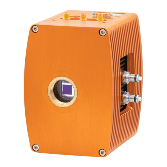
- Page 1 NINOX 640 SU Model: NXU-CL-640 USER MANUAL NINOX 640 SU/USER MANUAL/01-21/REV1.0...
-
Page 2: Table Of Contents
8.3 Acquiring a Live Image Sequence ................15 9. CONTROLLING THE CAMERA (XCAP) ................ 16 9.1 Exposure Time and Frame Rate ................16 9.2 Gain Mode ........................ 17 9.3 Trigger Mode ......................18 9.4 Thermoelectric Cooler (TEC) .................. 19 NINOX 640 SU/USER MANUAL/01-21/REV1.0... - Page 3 9.5 Manufacturers Data ....................20 10. XCAP CONTROL FEATURES ..................21 10.1 Saving Preset Configuration Settings ..............21 10.2 Contrast Modification (XCAP Std. Only) .............. 22 NINOX 640 SU/USER MANUAL/01-21/REV1.0...
-
Page 4: Introduction
Ninox 640 SU is the lowest noise camera available. With an ultra-low typical readout noise (rms) of 30e- and a typical dark current reading of <300e-/p/s at -80°C, the Ninox 640 SU improves even further on its noise performance. Raptor recommends that this manual be used to optimize camera operation. -
Page 5: Camera Care
— The camera’s sensor and circuits are sensitive to static discharge. Ensure that you are using a static strap or completely grounded at all times to release any static energy before you clean the window. CAUTION — Do not use acetone. NINOX 640 SU/USER MANUAL/01-21/REV1.0... -
Page 6: Specification
3. SPECIFICATION 3.1 Camera Overview The Ninox 640 SU is a 16-bit deep cooled SWIR camera. The camera has a response in the SWIR region from 0.9µm to 1.7µm. The Ninox 640 SU is an ultra-high sensitivity camera, offering a low dark current of <300 e/p/s with a typical readout noise of 30e-. -
Page 7: Design Overview
4. DESIGN OVERVIEW 4.1 Mechanical Model Units shown in mm and inches [in] PDF of mechanical model available from our website: https://www.raptorphotonics.com/products/ninox-640-su/ NINOX 640 SU/USER MANUAL/01-21/REV1.0... -
Page 8: Physical Interface
The camera has a standard C-mount that should easily screw onto any microscope port. 4.5 Mounting to a Tripod or Optical Table The camera has a ¼-20 BSW (Whitworth) threaded hole to mount to a tripod or an optical table. NINOX 640 SU/USER MANUAL/01-21/REV1.0... -
Page 9: Software Compatibility
5. SOFTWARE COMPATIBILITY This section outlines the options relating to software that are available for the Ninox 640 SU. 5.1 XCAP Compatibility Raptor works closely with EPIX who integrate all Raptor camera models into their XCAP Imaging Software package. XCAP is the core plug and play software package that is offered with the Ninox 640 SU. -
Page 10: Camera And Chiller Setup
1. Connect the T257P chiller to the Ninox 640 SU using the tubing provided. You will hear a click which indicates a solid connection. The polarity of the tubing connections does not matter. -
Page 11: Draining The Chiller, Camera And Tubing
Raptor. Shorter draining tubes will be supplied with the demo kit. Two draining tubes (with the appropriate mating connectors) need to be connected to both connecters on each of the camera, chiller and tubing to drain each individually. NINOX 640 SU/USER MANUAL/01-21/REV1.0... -
Page 12: Frame Grabber And System Requirements
PIXCI EB1 model. If using a laptop, EPIX offers base Camera Link frame grabbers for a laptop system, such as the ECB1/ECB1-34. NINOX 640 SU/USER MANUAL/01-21/REV1.0... -
Page 13: Xcap Imaging Software
A PIXCI Open/Close pop-up box will open as shown in Figure 2. Figure 2: PIXCI Open/Close. Click on “Camera & Format” that is highlighted in Figure 2 and a “PIXCI Open Camera & Format” box will appear, as shown in Figure 3. NINOX 640 SU/USER MANUAL/01-21/REV1.0... - Page 14 Figure 3: PIXCI Open Camera & Format. Using the dropdown menu highlighted, search for “Raptor Photonics Ninox 640 SU”. You will see the configuration for “Raptor Photonics Ninox 640 SU”. Selecting “Open w. Default Video Setup” will open the control panel with all control parameters set to the default states.
-
Page 15: Acquiring A Live Image Sequence
Clicking the “Live” button will grab a live image sequence which you will now see in the imaging window. The symbols in the control app discussed above are displayed in Figure 5. Figure 5: Checking Camera Connection and Acquiring a Live Image. NINOX 640 SU/USER MANUAL/01-21/REV1.0... -
Page 16: Controlling The Camera (Xcap)
9. CONTROLLING THE CAMERA (XCAP) The sections below will give information on using each control of the Ninox 640 SU, giving a description on how to use each control parameter and their effect on the camera’s performance. The software used to illustrate the camera controls is XCAP. -
Page 17: Gain Mode
Low gain mode provides the best dynamic range and can provide better images for high scene illumination e.g. daytime imaging or using large exposure times. The gain mode control is shown in Figure 10. Figure 10: Gain Mode Control. NINOX 640 SU/USER MANUAL/01-21/REV1.0... -
Page 18: Trigger Mode
When this mode is enabled, the “Trigger Polarity” (rising or falling edge) dropdown input box will become available. By default, the camera will run with a rising edge trigger polarity. A trigger delay can also be set when external trigger mode is enabled. Figure 11: Trigger Mode. NINOX 640 SU/USER MANUAL/01-21/REV1.0... -
Page 19: Thermoelectric Cooler (Tec)
9.4 Thermoelectric Cooler (TEC) The Ninox 640 SU uses a TEC to cool the sensor temperature of -80 ͦ C . The TEC status is shown in the “TEC” tab of the XCAP GUI, shown in Figure 13. The TEC control can be enabled/disabled from this tab. By default, the TEC will be enabled and set to a -80 ͦ... -
Page 20: Manufacturers Data
The “Info” tab displays the manufacturers data of the camera, such as the firmware version and serial number etc. The PCB and sensor temperature can be read back from this tab by clicking “Update Temp.” The “Info” tab is shown in Figure 15. Figure 15: Manufacturers Data. NINOX 640 SU/USER MANUAL/01-21/REV1.0... -
Page 21: Xcap Control Features
The overall settings file can then be saved and loaded in this tab also. Three preset states are the maximum number that can be saved in a settings file. Figure 16: Preset Configuration Settings. NINOX 640 SU/USER MANUAL/01-21/REV1.0... -
Page 22: Contrast Modification (Xcap Std. Only)
Histogram Percentile Endpoints” and click “preview”. The contrast modification will now be applied over the live image feed. The contrast can be adjusted using the low and high end percentile point controls. The default settings are usually adequate for most applications. Figure 18: Contrast Modification. NINOX 640 SU/USER MANUAL/01-21/REV1.0... - Page 23 NINOX 640 SU/USER MANUAL/01-21/REV1.0...
- Page 24 CORPORATE HEADQUARTERS Raptor Photonics LTD Willowbank Business Park Larne, Co Antrim BT40 2SF Northern Ireland PH: +44 2828 270141 www.raptorphotonics.com NINOX 640 SU/USER MANUAL/01-21/REV1.0...
Need help?
Do you have a question about the Ninox 640 SU and is the answer not in the manual?
Questions and answers