Advertisement
Quick Links
Advertisement

Subscribe to Our Youtube Channel
Related Manuals for Raptor Photonics OWL 640 M


Summary of Contents for Raptor Photonics OWL 640 M
- Page 1 OWL 640 M Model: OW1.7-VS-CL-LP-640 USER MANUAL...
-
Page 2: Table Of Contents
CONTENT CONTENT............................2 INTRODUCTION ........................3 SPECIFICATION ........................4 GETTING STARTED ........................6 EPIX XCAP ..........................8 MICRO-MANAGER ........................ 18 OW1.7-VS-CL-LP-640/USER MANUAL/08-20/REV1.4... -
Page 3: Introduction
INTRODUCTION Scope This manual covers the Owl 640 M digital camera and all applicable components. Raptor recommends that this manual be used to optimize camera operation. Camera Care Raptor cameras require no regular maintenance except occasional external cleaning of the sensor window (the glass window between the camera sensor and the microscope or lens). -
Page 4: Specification
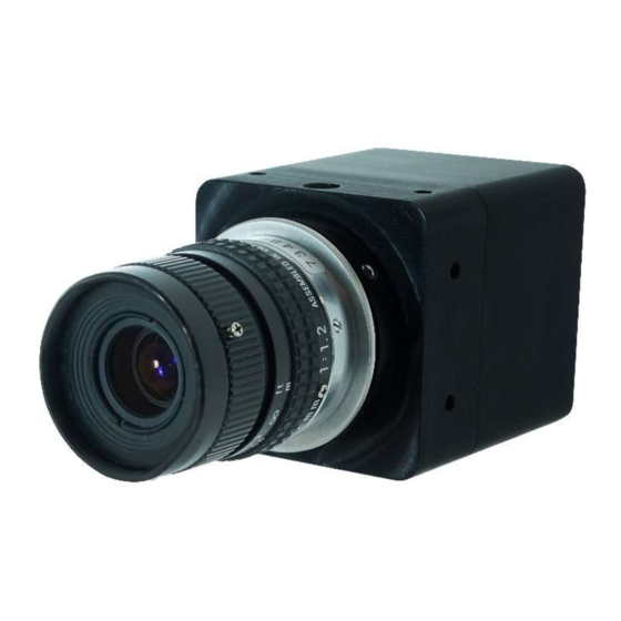
SPECIFICATION Camera Specification The OWL 640 M digital camera is designed for high-resolution applications requiring visible to SWIR imaging (400-1700nm). The OWL M camera uses an InGaAS sensor with a resolution of 640 x 512 in a 14-bit digital output. High-speed low-noise electronics provide linear response and sensitivity for rapid image capture. - Page 5 Mechanical Outline 3D drawings (STEP) are available upon request. OW1.7-VS-CL-LP-640/USER MANUAL/08-20/REV1.4...
-
Page 6: Getting Started
GETTING STARTED System Overview C-mount Power Trig out/SMA Trig in/SMA Camera Link Connector/SDR Mounting to Microscope The OWL 640 has a standard C-Mount that should easily screw onto any microscope port. Mounting to a tripod or optical table The camera has a ¼-20 BSW (Whitworth), threaded hole to mount to a tripod or an optical table. The image below shows an optical table mount with the ¼-20 BSW thread. - Page 7 - Software tested by Raptor Photonics - Software tested by other companies Blank - The camera has not been tested or is not supported by this software In this guide, there is a quick overview of XCAP (http://www.epixinc.com/support/files.php) and Micro- Manager (https://micro-manager.org).
-
Page 8: Epix Xcap
Figure 1: Open / Close 3. Select Close, and then Click on the Camera & Format button. 4. Using the dropdown menu scroll down and select Raptor Photonics OWL-CL-640 from the list (Figure 2). Selecting OK when done. Figure 2: Camera Selection... - Page 9 6. The camera controls are pre-configured in EPIX. 7. The control window on the right should reflect your chosen camera. For example, for the Owl 640, it should read - EPIX PIXCI E8DB: Raptor Photonics OWL-CL-640. If not, you need to select a different camera.
- Page 10 Figure 5: Image Capture 12. You should now see an image. On the bottom of the screen, you should see something similar to the following: Frame: 0 Size: 640 x 512 Resize 0.7x0.7 Video: 26.0fps Capture: 26.0 fps Display: 25.1fps. Figure 6: Live Image Capture Window OW1.7-VS-CL-LP-640/USER MANUAL/08-20/REV1.4...
- Page 11 Changing the settings on XCAP You have the ability to change several settings to control the camera through the tabs in the control window of the EPIX software. Exposure Click on the Gain Tab. There is an option for Auto Level Control (ALC). When Auto Level Control is unchecked, you can manually adjust the exposure and digital gain using the sliders or entering a specific value in the field.
- Page 12 Trigger Use this tab to select the Readout Mode, and a Fixed Frame Rate value. Figure 8: Trigger Tab Auto On this Tab, you can select the parameters for the Automatic Level Control, Including the speed, and spread of signal taken into account. In this mode, the FPGA of the camera will automatically adapt the exposure time and digital gain within the given frame rate to optimise the image quality.
- Page 13 Auto ROI Use this tab to set the Region of Interest (ROI) used for the Auto Level Control; ROI gain will set an overlay onto the image so you can track its position. By default, this will be set to account for the whole image.
- Page 14 Figure 12: Active ROI However, when we move the ROI box to the carpet, Figure 12, where the sun is shining the camera adjusts the exposure but the box becomes too dark to see any detail. This is an extreme example used to illustrate this feature.
- Page 15 Figure 14: NUC Off Figure 15: NUC On Thermoelectric Cooling (TEC). Use this tab to set and read back the sensor temperature. The optimum temperature should be set on start-up, for the OWL 640 should be 15°C. Figure 16: TEC Control OW1.7-VS-CL-LP-640/USER MANUAL/08-20/REV1.4...
- Page 16 4.10 Miscellaneous There are two features here, Video invert and Active Image Enhancement. Output video can be digitally inverted such that dark areas in the image will appear bright by checking the video invert box. Figure 17: Camera Information Output video can be digitally processed to provide image sharpening by checking the Active image enhancement box as shown in Figure 17.
- Page 17 4.11 Adjusting the image display (With XCAP Std only) The Viewing Pallet is not automatically adjusted in the XCAP software. This needs manually Configured to give the best display of the RAW image data from the camera. 1. Go to the Modify/Contrast Modification menu, Figure 19. 2.
-
Page 18: Micro-Manager
MICRO-MANAGER Micro-Manager is software for control of microscopes. It works with almost all microscopes, cameras and peripherals on the market, and provides an easy to use interface that lets you run your microscopy- based experiments. Micro-Manager runs as a plugin to ImageJ, is Open Source, and is free. It is a complete image acquisition and microscope control package, available for Windows, Mac and Linux, it is easy to install and configure right "out-of-the-box", with built-in functionality and user interface for most common tasks performed in a Life Science laboratory. - Page 19 Download and install Begin by installing the latest Micro-Manager. This can be done by going to the ‘downloads’ section of their website: www.Micro-Manager.org. You should select the latest nightly build for your operating system, found in the ‘Download Nightly Builds’ section. This will open a direct link to the Micro Manger FTP site where you can download most recently modified file.
- Page 20 Configuring Micro-Manager When first opening Micro-Manager for the first time you will see the window shown in (Figure 22). You need to make sure (none) is selected then click Ok. Figure 22: Hardware Configuration 1. Start the Hardware Configuration Wizard by going to tools then Hardware Configuration Wizard. Figure 23: Hardware Configuration Wizard OW1.7-VS-CL-LP-640/USER MANUAL/08-20/REV1.4...
- Page 21 2. Create a new configuration (figure 23) then look for the camera driver in the RaptorEPIX folder (shown in Figure 24), now click Next. Figure 24: Add a New Device 3. Continue to click Next until you are faced with the screen shown in Figure 24. 4.
- Page 22 Next time you open Micro-Manager you can simply select the saved Raptor Owl 640.cfg from the drop down menu (figure 26) then click Ok. Figure 26: Selecting Saved Camera Configurations OW1.7-VS-CL-LP-640/USER MANUAL/08-20/REV1.4...
- Page 23 Operating your camera using Micro-Manager Figure 27: Opening Screen 1. Click on snap (Figure 27) for Micro-Manager to open the viewing window as shown in Figure 28 Figure 28: Viewing Window OW1.7-VS-CL-LP-640/USER MANUAL/08-20/REV1.4...
- Page 24 Changing Camera settings All of the camera parameters are controlled within the Device/Property Browser; this can be accessed by selecting Tools from the menu bar then Device Property Browser… Figure 29: Camera Control Options From here, you can access all the camera settings. OW1.7-VS-CL-LP-640/USER MANUAL/08-20/REV1.4...
- Page 25 CORPORATE HEADQUARTERS Raptor Photonics LTD Willowbank Business Park Larne, Co Antrim BT40 2SF Northern Ireland PH: +44 2828 270141 www.raptorphotonics.com OW1.7-VS-CL-LP-640/USER MANUAL/08-20/REV1.4...
Need help?
Do you have a question about the OWL 640 M and is the answer not in the manual?
Questions and answers