Table of Contents
Advertisement
Quick-Change Installation and Operation Manual
Document #9620-20-c-dkgm dkft-03
C. Control and Signal Modules .................................................................................................. 3
1.
Product Overview .............................................................................................................. 3
1.1
Master Module ......................................................................................................................... 3
1.2
Tool Module ............................................................................................................................. 3
2.
Installation ......................................................................................................................... 5
2.1
Installing ................................................................................................................................... 5
2.2
Removal ................................................................................................................................... 5
2.3
EtherNet/IP Configuration ........................................................................................................ 6
2.4
Utility Schematic ....................................................................................................................... 6
3.
Product Information .......................................................................................................... 7
3.1
Master Module ......................................................................................................................... 7
3.1.1
3.1.2
3.1.3
3.1.4
3.1.5
3.1.6
3.1.7
3.1.8
3.2
Arc Prevention Circuit ............................................................................................................ 14
3.2.1
3.2.2
3.3
Tool Module ........................................................................................................................... 15
3.3.1
3.4
Tool-Side TSI ......................................................................................................................... 16
3.4.1
3.4.2
3.5
Software ................................................................................................................................. 18
4.
Operation ......................................................................................................................... 20
4.1
Recommended Sequence of Operation ................................................................................ 20
5.
Diagnostic Functions and Error Handling ..................................................................... 22
5.1
Power Status .......................................................................................................................... 22
5.2
Valve Power Status ................................................................................................................ 22
5.3
Error on Latch or Unlatch Output ........................................................................................... 22
5.4
"COMM OK" bit ...................................................................................................................... 22
5.5
"Tool Power is On" bit ............................................................................................................ 22
5.6
"Unlatch Enabled" bit.............................................................................................................. 22
6.
Maintenance ..................................................................................................................... 23
6.1
Pin Block Inspection and cleaning ......................................................................................... 23
6.2
Seal Replacement .................................................................................................................. 24
7.
Troubleshooting .............................................................................................................. 25
8.
Recommended Spare Parts and Accessories ............................................................... 26
9.
Specifications .................................................................................................................. 26
10.
Drawings .......................................................................................................................... 27
•
Pinnacle Park
1031 Goodworth Drive
Table of Contents
Class 1 Connection Information .............................................................................. 7
Integrated Web Server ............................................................................................. 7
IP Address Configuration ......................................................................................... 7
Ethernet Switch Settings .......................................................................................... 9
Ethernet Switch Diagnostics .................................................................................. 10
DIP Switches on the Master Module ..................................................................... 11
Module and Network Status LED .......................................................................... 12
Using Ethernet Quick-Connect .............................................................................. 13
Arc Prevention Circuit Behavior during Coupling .................................................. 14
Arc Prevention Circuit Behavior during Uncoupling .............................................. 14
Tool-ID Switches .................................................................................................... 15
TSI Behavior for Module with Firmware Version 2.52 or Later .............................. 16
TSI Behavior for Module with Prior to Firmware Version 2.52 .............................. 17
•
•
Tel: 919.772.0115
•
Fax: 919.772.8259
ia.com
C - 1
•
•
www.ati-ia.com
Email: info@ati-
Advertisement
Table of Contents

Related Manuals for ATI Technologies DKG-M


Summary of Contents for ATI Technologies DKG-M
-
Page 1: Table Of Contents
Quick-Change Installation and Operation Manual Document #9620-20-c-dkgm dkft-03 Table of Contents C. Control and Signal Modules ....................3 DKG-M and DKF-T—EtherNet/IP Control & Quick Connect Pass-through Modules ....3 Product Overview ......................3 Master Module ......................... 3 Tool Module ..........................3 Installation ......................... - Page 2 Quick-Change Installation and Operation Manual Document #9620-20-c-dkgm dkft-03 Glossary of Terms TERM DEFINITION Auxiliary Power 24VDC Power Supply interface provided that supports Switched and Unswitched circuits. Clear Errors An output supplied to the ATI Master EtherNet/IP node to clear all error conditions. An input indicating the status of the Tool-ID communication between Master and Tool Comm.
-
Page 3: Control And Signal Modules
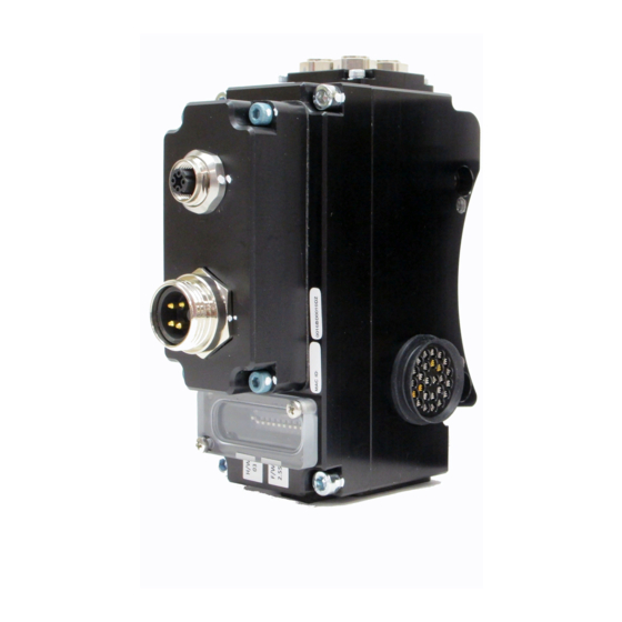
Quick-Change Installation and Operation Manual Document #9620-20-c-dkgm dkft-03 C. Control and Signal Modules DKG-M and DKF-T—EtherNet/IP Control & Quick Connect Pass-through Modules 1. Product Overview The EtherNet/IP modules enable the user to control and communicate with ATI's Heavy Automation Robotic Tool Changers using EtherNet/IP. - Page 4 Quick-Change Installation and Operation Manual Document #9620-20-c-dkgm dkft-03 Figure 1.1—DKG-M DKF-T EtherNet/IP Modules • • • • • • Pinnacle Park 1031 Goodworth Drive Apex, NC 27539 Tel: 919.772.0115 Fax: 919.772.8259 www.ati-ia.com Email: info@ati- ia.com C - 4...
-
Page 5: Installation
Quick-Change Installation and Operation Manual Document #9620-20-c-dkgm dkft-03 2. Installation The control/signal modules are typically installed by ATI prior to shipment. The steps below outline the field installation or removal as required. WARNING: Do not perform maintenance or repair on Tool Changer or modules unless the tool is safely supported or docked in the tool stand and all energized circuits (e.g. -
Page 6: Ethernet/Ip Configuration
Quick-Change Installation and Operation Manual Document #9620-20-c-dkgm dkft-03 CAUTION: It is recommended, not to use fasteners with pre-applied adhesive more than three times. Fasteners used more than three times may come loose and cause equipment damage. Discard fasteners used more than three times and install new fasteners with pre-applied adhesive. -
Page 7: Product Information
Document #9620-20-c-dkgm dkft-03 3. Product Information The DKG-M DKF-T modules enable the user to control and communicate with the Tool Changer through a network using an M12 D-coded 4-Pin EtherNet/IP interface connector. Control of the Tool Changer is realized through the Master node along with the reporting of various Tool Changer I/O. The Tool module supports Tool-ID reported through the Master and functions as a pass-through for EtherNet/IP and Auxiliary Power signals to downstream equipment. - Page 8 Quick-Change Installation and Operation Manual Document #9620-20-c-dkgm dkft-03 Octet settings. The gateway will be set to the default value of 0.0.0.0, and the subnet mask to the default value of 255.255.0.0. Method 2:Set IP address to a static value stored on the DKG’s Communication Settings web page (DIP switch 9 must be in the position).
-
Page 9: Ethernet Switch Settings
Quick-Change Installation and Operation Manual Document #9620-20-c-dkgm dkft-03 Figure 3.1—DKG Integrated Web Server Communication Settings Page 3.1.4 Ethernet Switch Settings The DKG module has an integrated Ethernet switch where the settings of two ports can be changed using the web server. The DKG module gets shipped with the following switch settings: Robot Side Port: Auto Negotiation:Enabled... -
Page 10: Ethernet Switch Diagnostics
On the Diagnostics page of the web server (see also Figure 3.2) the DKG-M module displays the current status of the robot and tool side port settings, as well as their diagnostic counters. This is the same information that is reported over the Ethernet Link Object 0xF6 in the EtherNet/IP protocol. -
Page 11: Dip Switches On The Master Module
Document #9620-20-c-dkgm dkft-03 Figure 3.2—DKG Integrated Web Server Diagnostics Page 3.1.6 DIP Switches on the Master Module The DKG-M module has 10 DIP switches which have the following functions: DIP 1 through 8: last octet of the DKGs IP address. See Section 3.1.3... -
Page 12: Module And Network Status Led
Quick-Change Installation and Operation Manual Document #9620-20-c-dkgm dkft-03 3.1.7 Module and Network Status LED The module status LED is identified on the module as “MS”. It provides device status for power and proper operation. Refer to Table 3.1 for an outline of this LED’s operation. The network status LED is identified on the module as “NS”. -
Page 13: Using Ethernet Quick-Connect
Quick-Change Installation and Operation Manual Document #9620-20-c-dkgm dkft-03 3.1.8 Using Ethernet Quick-Connect Using Ethernet Quick-Connect requires that the tool changer reports to the PLC when it is making electrical contact between master and tool before the PLC can start communicating to any downstream nodes. -
Page 14: Arc Prevention Circuit
Quick-Change Installation and Operation Manual Document #9620-20-c-dkgm dkft-03 3.2 Arc Prevention Circuit The DKG Module incorporates ATI’s exclusive Arc Prevention Circuit. The Arc Prevention Circuit extends the life of all electrical power contacts by eliminating arcing caused by inductive loads and high inrush current during coupling/uncoupling. -
Page 15: Tool Module
Quick-Change Installation and Operation Manual Document #9620-20-c-dkgm dkft-03 Figure 3.6—Arc Prevention Circuit Power-Off Timing 3.3 Tool Module In addition to providing Tool-ID, the Tool module also functions as a pass-through for EtherNet/IP and Auxiliary Power signals to downstream equipment, for more details refer to Section 10—Drawings. -
Page 16: Tool-Side Tsi
3.4.1 TSI Behavior for Module with Firmware Version 2.52 or Later The DKG-M DKF-T modules with firmware 2.52 or later, rely on the status of the Ready-To- Lock (RTL) sensors, the Tool Present Signal, and the TSIV input to determine when it is appropriate to unlatch the Tool. -
Page 17: Tsi Behavior For Module With Prior To Firmware Version 2.52
3.4.2 TSI Behavior for Module with Prior to Firmware Version 2.52 The DKG-M DKF-T modules with firmware prior to 2.52, rely on the status of the Ready-To- Lock (RTL) sensors and the TSIV input to determine when it is appropriate to unlatch the Tool. -
Page 18: Software
An I/O bitmap for the Master node is provided in the table below. The default setting from the factory for the Master module is IP Address 136.129.1.1. Table 3.5—I/O Bitmap, Robot Inputs from ATI Master, (9121-DKG-M), EtherNet Default IP Address 136.129.1.1... - Page 19 Quick-Change Installation and Operation Manual Document #9620-20-c-dkgm dkft-03 Table 3.1—I/O Bitmap, Robot Outputs to 9121-DKG-M Module, Ethernet Default IP Address 136.129.1.1 Byte Bit# Name Description/Function Latch (Lock) Latch Solenoid Valve Output Unlatch (Unlock) Unlatch Solenoid Valve Output (Reserved) Clear Errors...
-
Page 20: Operation
This recommended Sequence of Operations procedure is to be used as a general guide when programming a robot or PLC for use with a Tool Changer and DKG-M DKF-T control/signal modules. This procedure is intended for "automatic" modes used during normal application processes. - Page 21 Quick-Change Installation and Operation Manual Document #9620-20-c-dkgm dkft-03 6. Robot moves away from the Tool Stand with the Tool Changer coupled. a. The TSI limit switch becomes deactivated, and the TSIV input goes false b. Unlatch Enabled becomes false. 7. Normal operation a.
-
Page 22: Diagnostic Functions And Error Handling
Quick-Change Installation and Operation Manual Document #9620-20-c-dkgm dkft-03 5. Diagnostic Functions and Error Handling There are several diagnostic functions that can have an effect on the input bitmap and influence the Tool Changer control. 5.1 Power Status The DKG module continuously monitors the voltage of its interface and sensor power supply. If the voltage is between 11V and 25V the “Input and Logic Power Good”... -
Page 23: Maintenance
Quick-Change Installation and Operation Manual Document #9620-20-c-dkgm dkft-03 6. Maintenance Once installed the operation of the EtherNet/IP modules is generally trouble free. The modules are not designed to be field serviced as all point-to-point wiring connections are soldered. Component replacement is limited to the V-Ring seal on the Master. -
Page 24: Seal Replacement
Quick-Change Installation and Operation Manual Document #9620-20-c-dkgm dkft-03 NOTICE: Do not use an abrasive media, cleaners, or solvents to clean the contact pins. Using abrasive media, cleaners, or solvents will cause erosion to the contact surface. Clean contact surfaces with a vacuum or non-abrasive media such as a nylon brush (ATI part number 3690-0000064-60). -
Page 25: Troubleshooting
Quick-Change Installation and Operation Manual Document #9620-20-c-dkgm dkft-03 7. Troubleshooting Refer to the table below for troubleshooting information: Symptom Possible Cause / Correction Unit will not lock or Verify that ball bearings are moving freely. Clean and lubricate as needed (see Tool Changer unlock Manual Maintenance Section). -
Page 26: Recommended Spare Parts And Accessories
DKF Tool Module Assembly 9121-DKF-T Optional Accessories Closure Cap for Female Mini Receptacles 3690-0000049-00 See drawings in Section 10 of this manual for spare parts directly associated with the DKG-M/DKF-T modules. 9. Specifications DKG EtherNet/IP Master Module Factory Default Configuration I/P Address: 136.129.1.1... -
Page 27: Drawings
Quick-Change Installation and Operation Manual Document #9620-20-c-dkgm dkft-03 10. Drawings • • • • • • Pinnacle Park 1031 Goodworth Drive Apex, NC 27539 Tel: 919.772.0115 Fax: 919.772.8259 www.ati-ia.com Email: info@ati- ia.com C - 27... - Page 28 Quick-Change Installation and Operation Manual Document #9620-20-c-dkgm dkft-03 • • • • • • Pinnacle Park 1031 Goodworth Drive Apex, NC 27539 Tel: 919.772.0115 Fax: 919.772.8259 www.ati-ia.com Email: info@ati- ia.com C - 28...
- Page 29 Quick-Change Installation and Operation Manual Document #9620-20-c-dkgm dkft-03 • • • • • • Pinnacle Park 1031 Goodworth Drive Apex, NC 27539 Tel: 919.772.0115 Fax: 919.772.8259 www.ati-ia.com Email: info@ati- ia.com C - 29...
Need help?
Do you have a question about the DKG-M and is the answer not in the manual?
Questions and answers