Table of Contents
Advertisement
Quick Links
Metrinet Controller
With Cellular Modem
Home Office
Analytical Technology, Inc.
6 Iron Bridge Drive
Collegeville, PA 19426
Phone: 800-959-0299
610-917-0991
Fax:
610-917-0992
Email: sales@analyticaltechnology.com
Web: www.Analyticaltechnology.com
O & M Manual
European Office
ATI (UK) Limited
Unit 1 & 2 Gatehead Business Park
Delph New Road, Delph
Saddleworth OL3 5DE
Phone: +44 (0)1457-873-318
Fax:
+ 44 (0)1457-874-468
Email: sales@atiuk.com
Advertisement
Table of Contents
Troubleshooting

Related Manuals for ATI Technologies MetriNet Q52


Summary of Contents for ATI Technologies MetriNet Q52
- Page 1 O & M Manual Metrinet Controller With Cellular Modem Home Office European Office Analytical Technology, Inc. ATI (UK) Limited 6 Iron Bridge Drive Unit 1 & 2 Gatehead Business Park Collegeville, PA 19426 Delph New Road, Delph Phone: 800-959-0299 Saddleworth OL3 5DE 610-917-0991 Phone: +44 (0)1457-873-318 Fax:...
-
Page 2: Table Of Contents
Table of Contents PART 1 - INTRODUCTION ......... 4 4.1 G ............23 ENERAL 4.2 C ........23 ONTROLLER NTERFACE 1.1 G ............4 ENERAL 4.3 M-N ........24 SSIGNMENT 1.2 S ........5 YSTEM OMPONENTS 4.4 C ......24 ONTROLLER ROGRAMMING PART 2 - SPECIFICATIONS ......... - Page 3 ABLE OF IGURES 1 – M 3 M-N ..............5 IGURE ETRI YSTEM WITH ODES 2 – 1 ................9 IGURE YSTEM ANEL 3 –5 - 8 N ................10 IGURE YSTEM ANEL 4 - E ................11 IGURE NCLOSURE IMENSIONS 5 - W ....................
-
Page 4: Part 1 - Introduction
Part 1 - Introduction General The MetriNet is an integrated water quality system designed for potable water distribution monitoring. The primary function is to log water quality measurements. Data may be manually collected using an SD card built into each controller. Interface options are also available to retrieve data from the unit via Modbus RTU/RS-485, Modbus TCP or Ethernet IP. -
Page 5: System Components
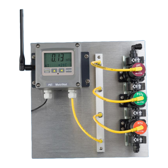
MetriNet Water Quality System Part 2 - Introduction M-Nodes are installed in modular flow chambers, secured with twist-lock pins on the front of the node. Each node requires one chamber and chambers clamp together with locking rings on each end. Push-to-connect fittings are installed on each end but end fittings contain 1/8” NPT female threads to accommodate other fittings. - Page 6 MetriNet Water Quality System Part 2 - Introduction Flow Chamber Assembly Typical M-Node MetriNet Controller Bus Bar & Sensor Cables Photo of bus bar And cables O&M Manual Rev-C (05/20)
-
Page 7: Part 2 - Specifications
Part 2 - Specifications MetriNet Controller (Q52) Displayed Parameters Four-digit node measurement (ppm, NTU, mV, etc.) (for each M-Node) Sensor temperature, -10.0 to 55.0 °C (14 to 131 ºF) Other measurement displays on lower line dependent on specific sensor 0.75” (19.1 mm) high 4-digit main display with sign Display 12-digit secondary display, 0.3"... -
Page 8: Metrinet Performance Specifications (Q52)
MetriNet Water Quality System Part 2 - Specifications Weight 1 lb. (0.45 kg) MetriNet Performance Specifications (Q52) Accuracy 1% of range Repeatability 0.5% of range Sensitivity 0.1% of range Non-Linearity 0.1% of range Warm-up Time 3 seconds to rated performance (electronics only) Supply Voltage Effects +/- 0.05% of range MetriNet Flow Chambers... -
Page 9: Part 3 - Installation
Part 3 - Installation System Mounting If your MetriNet system was purchased as a complete assembly mounted on a non-metallic plate, all that’s needed is to mount the plate. Systems with up to 4 Nodes are supplied on a 14” x 14” plate, ¼”... -
Page 10: Figure 3 -5 - 8 Nodes
MetriNet Part 3 – Installation Water Quality System Figure 3 –5 - 8 Node System Panel O&M Manual Rev-C (05/20) -
Page 11: 3.2 Controller Mounting
MetriNet Part 3 – Installation Water Quality System 3.2 Controller Mounting MetriNet controllers are supplied with a PVC mounting plate that attaches to the back of the enclosure. 4.38 2.61 (111.2) (66.3) MENU ENTER 4.38 #10-32 UNF 2.61 (111.2) (4 PLACES) (66.3) FRONT VIEW BACK VIEW... -
Page 12: Wall Or Pipe Mount
MetriNet Part 3 – Installation Water Quality System Wall or Pipe Mount A PVC mounting bracket with attachment screws is supplied with each controller. The bracket is attached to the rear of the enclosure. The bracket provides for either wall or pipe mounting as shown in Figure X. Note that bracket slots are for u-bolts with ¼-20 threads. -
Page 13: Flow System Mounting
MetriNet Part 3 – Installation Water Quality System Flow System Mounting Flow chambers for MetriNet systems are modular so the size will vary depending on the number of M-Nodes to be used. Flow chambers should always be mounted vertically, with sample entering at the bottom and exiting at the top. -
Page 14: Bus Bar Mounting
MetriNet Part 3 – Installation Water Quality System 5.44" 138mm 5.75" w/o DIN RAIL 146mm BRACKET 2.60" 2.76" 66mm 70mm FLOWCELL C-C DISTANCE TYP. Figure 8 – Flow Chamber Dimensions Bus Bar Mounting MetriNet controllers connected to only one sensing node will not use a bus bar. All systems with more than one sensor will need at least one. -
Page 15: Sample Connection
MetriNet Part 3 – Installation Water Quality System Sample Connection Flow systems are designed to use ¼” OD polyurethane or other semi-rigid tubing. Sample is normally coming from pressurized water pipe and flow systems can handle sample pressures as high as 100 PSIG. However, we recommend that inlet pressure be reduced to about 30 PSI if source water pressure is above 60 PSI. -
Page 16: Intermittent Sampling, Cycle Mode
MetriNet Part 3 – Installation Water Quality System Intermittent Sampling, Cycle Mode Water samples for MetriNet systems often run continuously, controlled at 200 ml/min. by a flow control device in the outlet assembly. However, the MetriNet controller can turn on flow intermittently to greatly reduce water consumption, operating in “Cycle Mode”... -
Page 17: Electrical Connections
MetriNet Part 3 – Installation Water Quality System If a system is using solenoid flow control, be sure that the valve delay is long enough so that fresh sample reaches sensors for at least 30 seconds. For estimating the required time, you must take into account the length of your sample line. -
Page 18: Digital Input
MetriNet Part 3 – Installation Water Quality System 3.81 Digital Input Under some conditions, a user may wish to initiate a measurement cycle using an externally generated contact closure. As an example, an alarm from another device might be used to tell the MetriNet controller to take a reading. -
Page 19: Power In 115Vac Unit
MetriNet Part 3 – Installation Water Quality System NOTE – When power is first applied to the instrument, the modem powers up and configures itself, so current consumption is high. If making active current measurements, you must wait about 2 minutes after power is first applied to see the true steady state current. -
Page 20: Battery Pack Sizing
MetriNet Part 3 – Installation Water Quality System C-Solenoid Power - At 12VDC, the flow solenoids is pulse driven for only an instant, 2A @ 200 ms) to change state. The solenoid is used to limit water loss. D-Modem Power – At 12VDC, the modem consumes 100 mA max for about 2 minutes max at each call. -
Page 21: Installation Site Factors
MetriNet Part 3 – Installation Water Quality System For example, one of the variations of the MetriNet is available directly with 8 common alkaline D- cell batteries, each with 19 Ahr of available power. This represents a power source of about 12VDC @ 19 Ahr total. -
Page 22: M-Node Preparation
MetriNet Part 3 – Installation Water Quality System M-Node Preparation Sensor nodes are packed individually and some require preparation prior to use. Some require removal of a wetting cap and some simply require installation into the flow chamber. The table below provides guidance. -
Page 23: Part 4 - Operation
Part 4 – Operation General Check to see that sample is running through the flow assembly. Sample flow is controlled at 200 ml./min. If the system was not purchased with the flow control element, adjust the flow through the system with a valve placed on the outlet side of the flow assembly. Recheck all wiring and verify that the power supply is in the range of 12-24 VDC for external DC systems, and 12VDC for battery systems. -
Page 24: M-Node Assignment
MetriNet Part 4 – Operation Water Quality System M-Node Assignment Each measurement node must have a unique sensor number. By default, all sensors are shipped at address #1. If there is more than one sensor in your system, a new sensor number must be assigned to each additional sensor, 1-8. -
Page 25: Figure 16 - Controller
MetriNet Part 4 – Operation Water Quality System Start MENU MENU MENU MENU MENU MENU MEASURE INFO SENSOR CONFIG OPTIONS SECTIONS (display only) ENTER ENTER ENTER ENTER S1 Temperature Log Mode Q52 Unit ID Cal S1 Auto Scan S1 mV Hold Log Interval Cal Zero S1... -
Page 26: Measure Menu
MetriNet Part 4 – Operation Water Quality System 4.41 MEASURE Menu The default controller menu is MEASURE. This menu is display-only. When left alone, the unit will return to the MEASURE menu after 30 minutes. Note that the main display variable will scan through each node automatically. -
Page 27: Info Menu
MetriNet Part 4 – Operation Water Quality System 4.42 INFO Menu The INFO menu provides some basic information on the MetriNet controller, also called the Q52. These menu items are for reference only. Q52 UNIT 10 Specific ID of this Q52. User set. 13:59:40 Hour/Minute/Sec time. -
Page 28: Config Menu
MetriNet Part 4 – Operation Water Quality System Alarm B S1 Setpoint for Alarm B. User may define a second alarm limit above which the B alarm will be shown in the MEASURE menu. User may define a “slope” alarm limit. If the sensor slope falls below that Slp Alrm S1 limit after a calibration, Alarm C is shown in the MEASURE menu. -
Page 29: Options Menu
MetriNet Part 4 – Operation Water Quality System Valve Delay If the optional solenoid is used to turn flow on and off, the valve delay value defines the delay time, starting from when the solenoid is opened, before sensor nodes are powered up to make measurements. Delay time depends on length of sample lines. - Page 30 MetriNet Part 4 – Operation Water Quality System Host Comms Enables internal cell modem or other digital communications interface if installed. For this cellular unit, should be set to “Cell.” Xmit Start Defines when the first data transmission by the cell modem will occur. Range is 00-23, 00=midnight, 23=11 PM.
-
Page 31: Set Passwords
MetriNet Part 4 – Operation Water Quality System Set Passwords MetriNet systems are designed with 2 levels of password protection to prevent unauthorized adjustments. There is one Administrator password and up to 5 separate User passwords. All passwords are numerical, consisting of 4 digit numbers. As shipped, controllers are not password protected. -
Page 32: Part 5 - Data, Alarm & Event Log
Part 5 – Data, Alarm & Event Log General The primary purpose of a MetriNet system is to monitor water quality parameters and log the data. The data may then be either transmitted to a remote data storage cloud site by modem or collected manually by writing data to the SD RAM card located in the controller. -
Page 33: Alarm File Format
MetriNet Part 5 – Data, Alarm, Event Log Water Quality System Data Record Radio Model HE910-D IMEI Number 35613607 4512551 SIM Number 89011702 27202478 6805 Signal Level Bit Error Rate Supply Voltage 12.1 Latitude 5453.34N Longitude 8531.52W Date HH:MM:SS Temp Sensor 1 Sensor 2 Sensor 3 Sensor 4 Sensor 5 Sensor 6 Sensor 7 Sensor 8 9/23/2018 15:10:58... -
Page 34: Event File Format
MetriNet Part 5 – Data, Alarm, Event Log Water Quality System There is an assumption here that any alarm that is uploaded is also immediately acknowledged and acted up by the user’s data site, as they will know the instant an alarm record appears in the package upload. -
Page 35: Local Data Storage Capacity
MetriNet Part 5 – Data, Alarm, Event Log Water Quality System Controllers are supplied with 2 GB SD cards. To retrieve data manually, simply write stored data to the SD card using the “Save to Crd” routine in the OPTIONS menu. Many new computers have micro-SD slots while others will only accept the larger format SD card. - Page 36 MetriNet Part 5 – Data, Alarm, Event Log Water Quality System So, with the minimum of 2.5K of data moved as overhead for the cell connection and no data file, a MetriNet that calls in twice a data moves about 150K of just connection/registration data per month (5K x 30) just to establish proper connections.
-
Page 37: Part 6 - Cellular Setup
Part 6 – Cellular Setup SIM Card Installation MetriNet controllers equipped with cellular modems require a SIM card with data service from a national or global service provider. Systems supplied for evaluation purposes will be delivered with a global SIM card already installed and ready to operate. For long term installations, users may continue to lease data service from ATI or can arrange their own data services from another supplier. -
Page 38: Controller Programming
MetriNet Part 6 – Cellular Setup Water Quality System Modem SIM Card Antenna Cable Figure 22 – MetriNet Cellular Modem Board with SIM Card After installing the SIM card, plug the terminal board/modem assembly back into the display board. If you carefully line up the 4 corner screw locations with the standoffs on the display board, the multi-pin connector between the two boards will align properly. - Page 39 MetriNet Part 6 – Cellular Setup Water Quality System Clear Log This routine clears all data stored in flash memory as well as the data that is held in the cell modem flash memory. Once cleared, it cannot be recovered. Verify that all data has been saved (or is not needed) prior to clearing the log.
-
Page 40: Part 7 - Cellular Configuration Utility
Part 7 – Cellular Configuration Utility General The ATI Q52 Utility is a PC application program that is used to setup and configure the MetriNet Cell Modem option for a specific customer application. It also includes diagnostic troubleshooting capability required to assure proper operation or to monitor operation should a problem occur. Requirements: Windows based PC FTDI-232R-3V3-AJ USB Communications Cable... -
Page 41: Figure 23 - Metri Net Pc C
MetriNet Part 7 – Cell Config Utility Water Quality System Figure 23 – MetriNet PC Cable Connection Once the device is ready for use, click on the ATI Icon to start the program. The ATI Splash screen will be displayed, then the following window will open. Figure 24 –... -
Page 42: Figure 26 - Wq Hub Setup
MetriNet Part 7 – Cell Config Utility Water Quality System The program will attempt to communicate with the Cell Modem Option. An associated configuration file is loaded. You can also manually select a configuration file by clicking on Open and selecting a configuration file. You must have the correct configuration file for the device and version software running on it. -
Page 43: Figure 27 - Wq Hub Setup
MetriNet Part 7 – Cell Config Utility Water Quality System Click on the Manage Instruments ICON. This will bring up the following screen. Figure 27 – WQhub Setup. Instrument Settings. Simply cut and paste the Web Address, Modem Login Name and Modem Login Password from this web page into the ATI Q52 Utility fields. -
Page 44: Part 8 - Metrinet Troubleshooting
Part 8 – MetriNet Troubleshooting The following section can be used to correct problems associate with modem communication problems. With the PC utility connected, click on the Tools option on the menu bar and select Com Debug. Figure 28 – Troubleshooting - The MetriNet Comm Debug Feature. An additional window will appear. -
Page 45: Figure 30 - Troubleshooting
MetriNet Part 8 – MetriNet Troubleshooting Water Quality System The above example shows that there is no SIM card installed in the radio modem. When there is no SIM card, data communications to the cell network is not possible. In the example below, the response indicates that an incorrect APN name is entered. -
Page 46: Figure 32 - Troubleshooting
MetriNet Part 8 – MetriNet Troubleshooting Water Quality System The next example shows that the radio modem is getting out to the network, but having a problem logging onto the file server. If the process hangs at this step, check the WEB address, login name and the login password to make sure they are correct. -
Page 47: Figure 34 - Troubleshooting
MetriNet Part 8 – MetriNet Troubleshooting Water Quality System One bit of data that is displayed is the signal quality as shown below (+CSQ: 11,1). This indicates how good the connection is from the radio modem to the cell tower. A value of 10 or more is good. -
Page 48: Spare Parts
Spare Parts Part No. Description Electronics 00-1795 MetriNet Controller, 12-24 VDC with SD Card 00-1811 MetriNet Controller, 12V Battery with SD Card 00-1796 MetriNet Controller, 12-24 VDC with SD Card & Modem 00-1812 MetriNet Controller, 12V Battery with SD Card & Modem 00-1885 MetriNet Controller, 12-24 VDC with SD Card &... - Page 49 MetriNet Water Quality System Misc Components 44-0260 Pg9 Cord Grip (each) 44-0009 Pg11 Cord Grip (each) O&M Manual Rev-C (05/20)
- Page 50 PRODUCT WARRANTY Analytical Technology, Inc. (Manufacturer) warrants to the Customer that if any part(s) of the Manufacturer's equipment proves to be defective in materials or workmanship within the earlier of 18 months of the date of shipment or 12 months of the date of start- up, such defective parts will be repaired or replaced free of charge.
- Page 51 WATER QUALITY MONITORS GAS DETECTION PRODUCTS Dissolved Oxygen Ammonia Carbon Monoxide Free Chlorine Hydrogen Combined Chlorine Nitric Oxide Total Chlorine Oxygen Residual Chlorine Dioxide Cl2 Phosgene Potassium Permanganate Bromine Chlorine Dissolved Ozone Chlorine Dioxide pH/ORP Fluorine Conductivity Iodine Hydrogen Peroxide Acid Gases Peracetic Acid O Ethylene Oxide...
Need help?
Do you have a question about the MetriNet Q52 and is the answer not in the manual?
Questions and answers