Table of Contents

Related Manuals for HydroSure 100205202


Summary of Contents for HydroSure 100205202
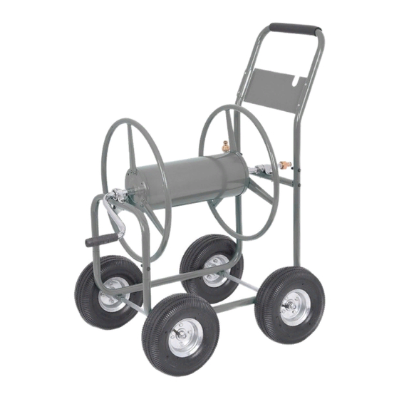
- Page 1 HydroSure Hose Reel Cart SKU: 100205202 Capacity: Specifications: 13mm (1/2”) = 125m Height - 38.5” (98cm) 19mm (3/4”) = 70m Width - 22” (56cm) 25mm (1”) = 30m Length Incl. Handle - 33” (84cm) Length Excl. Hanlde - 25” (64cm)
- Page 2 Package Contents...
- Page 3 Assembly Instructions Insert the two Side Frame (B) into the U-Tube (A). In- sert Bolt (P) into one of the holes of the U-Tube and tighten with Lock Nut (R) using the provided Wrench (U) and Allen Wrench (V). Repeat on the other side. Place Rear Cross Tube (C), with the holes facing up, between Side Frames (B).
- Page 4 Making sure the Tire Stem faces outward, slide the Pneumatic Tires (E) on end of the Axles. Secure the tires with Washers (T) and Lock Nuts (S) on the end of the Axle with the Wrench (U). NOTE: Do not over tighten the Lock Nut. Insert Handle (F) into the ends of the Side Frames (B).
- Page 5 Locate the Reel Flange (H) and place it on one end of the Hose Drum (I). Secure the Reel Flange and Hose Drum together using 3 Bolts (P). Repeat for the other Reel Flange. Slide the In/Out Tube (J) into the centre hole of the Hose Drum Insert the long end of the J-Bolt (K) into one of the remaining two holes on the end of the Hose Drum.
- Page 6 Insert the Crank Hub End of the Hose Drum into the Bearing Seat (G) that is attached to the U-Tube. Locate the Bearing Seat (G) on the IN/Out Tube to secure the Hose Coupling End of the Hose Drum to the Rear Cross Tube (C).
- Page 7 Insert Crank (L) into the Crank Hub of the Hose Drum. Align the holes in the Crank with the holes in the Crank Hub and secure using Bolt (Q) and Nut (R).
Need help?
Do you have a question about the 100205202 and is the answer not in the manual?
Questions and answers