Table of Contents
Advertisement
Quick Links
2021/04/17 23:32
Reconfigurable Laser
Servo
Model No. D2-125
Document Revision: 4.1
Document Last Updated on 2021/03/02 17:06
Please read
Limited Warranty
and Cautions
prior to operating the
Reconfigurable Servo.
Quick start for D2-125.
D2-125 web page.
Description
The D2-125 Reconfigurable Laser Servo contains a tunable PI
signal. The error signal is either an amplified version of the Error Input signal (side-lock mode) or an
amplified version of a demodulated Error Input (optional peak-lock mode). In both modes, a DC Offset
is summed to the error signal, allowing the user to select the zero-crossing and thus the lock point.
The error signal can also be inverted via a front-panel switch. Additionally, the Laser Servo has an
internal ramp generator for sweeping the output and computer control functionality to make and
break lock and directly control the output voltage.
The main component in the Reconfigurable Laser Servo is the PI
feedback has standard proportional (P), integral (I), and differential (D) feedback with a second
integral feedback (I) providing the PI
at low frequencies. With integrator frequencies tunable from 2 MHz down to 10 Hz, the Laser Servo
can be optimized to a wide variety of plants and servo loops. With the Peak Lock option, the Laser
Servo can demodulate a provided 4 MHz dither signal to enable slope-detection for locking to signal
minima and maxima. The Laser Servo can be used to lock a laser's current or PZT to an
interferometer or an optical transition. With peak-lock, the Laser Servo can perform Pound-Drever-Hall
(PDH) locking to an optical cavity. The Reconfigurable Laser Servo uses basic voltage inputs and
outputs. As a result, it can be used with lasers or with any voltage-tunable device with an error signal.
The Laser Servo can be unlocked by a computer (via TTL control) to jump the output voltage to a set
voltage difference from the current lock point, or to a specific voltage. This feature can be used to
jump the laser frequency a known distance away and then relock to the original or a new lock point
frequency. This feature can be used for auto-locking or relocking routines.
The Laser Servo has an internal sweep generator to sweep the laser frequency prior to lock.
Product Manuals - https://www.vescent.com/manuals/
1/18
and
General Warnings
D2-125 (web page)
2
D transfer function. The double integration is used to boost gain
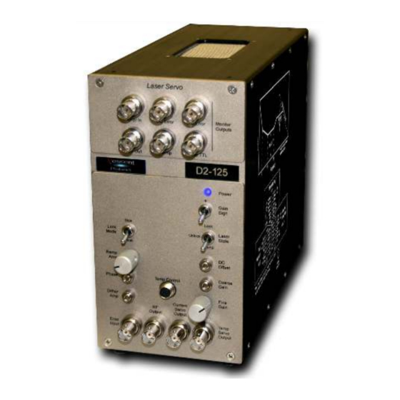
Fig. 1: D2-125
2
D loop filter for tight locking to an error
2
D loop filter, which means that the
Reconfigurable Laser Servo
Advertisement
Table of Contents

Related Manuals for Vescent Photonics D2-125


Summary of Contents for Vescent Photonics D2-125
- Page 1 Fig. 1: D2-125 Description The D2-125 Reconfigurable Laser Servo contains a tunable PI D loop filter for tight locking to an error signal. The error signal is either an amplified version of the Error Input signal (side-lock mode) or an amplified version of a demodulated Error Input (optional peak-lock mode).
-
Page 2: Absolute Maximum Ratings
Error Signal. This is often referred to as peak-locking. If purchased with the Peak Lock option, the Laser Servo can still be used in side-lock mode. A front panel switch controls whether the D2-125-PL is in side-lock or peak-lock mode. When in side-lock mode the modulation / demodulation circuitry is disabled. -
Page 3: Specifications
2021/04/17 23:32 3/18 Reconfigurable Laser Servo Specifications Value Units Input and Output Impedance Ω Output Voltage (main and aux) ±10 <5 nV/√Hz Input Voltage Noise Max Input Voltage DC Level ±500 Max Input Voltage Signal Amplitude ±500 >10 Bandwidth Proportional Gain (ref to DC Error) -66 to +6 Proportional Gain (ref to Input Error) -40 to +32... -
Page 4: Monitor Section
Last update: 2021/03/02 17:06 d2:laser_servo https://www.vescent.com/manuals/doku.php?id=d2:laser_servo Fig. 2: Schematic drawing of the front and back panels of the D2-125 Monitor Section Located at the top of the front panel, the monitor section contains 6 BNC outputs for monitoring various signals used by the Laser Servo. The logic of the monitors is shown in figure... - Page 5 2021/04/17 23:32 5/18 Reconfigurable Laser Servo Fig. 3: Monitor output logic Error In The ERROR IN monitor is a buffered and filtered version of the ERROR INPUT. The monitor has a 300 kHz low-pass filter. DC Error The signal from ERROR IN (after demodulation if in PEAK LOCK mode) is amplified by 26 dB (x20). The amplified signal is summed with both the DC OFFSET as set on the front panel and the back-panel DC OFFSET INPUT.
-
Page 6: Front Panel
Last update: 2021/03/02 17:06 d2:laser_servo https://www.vescent.com/manuals/doku.php?id=d2:laser_servo The RAMP TTL is a trigger synchronous with the ramp. It is usually used to trigger an oscilloscope while sweeping the SERVO OUTPUT. The RAMP TTL signal is also available on the back panel as a dedicated trigger output. - Page 7 2021/04/17 23:32 7/18 Reconfigurable Laser Servo Gain Sign (two-position switch) The GAIN SIGN reverses the sign of the signal input from ERROR INPUT and should be used if the desired lock-point has the wrong slope (loop is providing positive feedback instead of negative feedback).
-
Page 8: Right Side Panel
Ramp Offset Fine Fine adjust to the center of the ramp signal and the DC Voltage output in UNLOCK mode. Right Side Panel Fig. 4: Side panel of D2-125 showing transfer function and corner adjustments. https://www.vescent.com/manuals/ Printed on 2021/04/17 23:32... - Page 9 2021/04/17 23:32 9/18 Reconfigurable Laser Servo Fig. 5: Schematic of the configuration transfer function and user-controls. The feedback loop is defined by the Gain vs Frequency plot shown above. ƒ , ƒ and ƒ define three corners in the transfer function. ƒ and ƒ...
- Page 10 Last update: 2021/03/02 17:06 d2:laser_servo https://www.vescent.com/manuals/doku.php?id=d2:laser_servo knob must be in the LOW FREQ position. Second Integrator (TOP) Sets the frequency of the second integrator (ƒ ). This knob only selects the higher-frequency positions (20 kHz - 2 MHz). To set ƒ to lower frequencies, this knob must be placed in the LOW FREQ position.
- Page 11 2021/04/17 23:32 11/18 Reconfigurable Laser Servo Fig. 6: Certain rarely used controls are only accessible by removing the right-side panel, as shown in the figure above. Fig. 7: VPN00211 board. Selector DIP Switch Array: Ramp→Aux / Ramp→Servo (2-position slider switch) This 2-position slider switch is only accessible by removing the right side panel (see above) and sets whether the ramp is applied to the SERVO OUTPUT or the AUXILIARY SERVO OUTPUT.
- Page 12 In MASTER MODE (jumper on) the ramp is generated internally and is sent out to the RAMP I/O port for driving other D2-125 Laser Servos configured in SLAVE MODE. The amplitude of the slave ramp is about -5x of the master ramp input (at slave Ramp Amp maximum).
-
Page 13: Back Panel Section
2021/04/17 23:32 13/18 Reconfigurable Laser Servo has passed since the previous relock attempt. Mode A,B,C These three 2-position slider switches are only accessible by removing the right side panel (see above) and sets the Hold Time and N+1 Relock Time described above. The 3 positions, A,B,C form a binary scale factor given by the table below: Hold Time N+1 Relock Time... - Page 14 Last update: 2021/03/02 17:06 d2:laser_servo https://www.vescent.com/manuals/doku.php?id=d2:laser_servo Absolute Jump TTL (BNC) When asserted HIGH (5V) while in LOCK mode, ABSOLUTE JUMP takes the Laser Servo out of lock and conveys the negative of the voltage on LASER JUMP AMPLITUDE to the SERVO OUTPUT. Thus, a 1 V input to LASER JUMP AMPLITUDE applies -1 V to SERVO OUTPUT.
- Page 15 RAMP IN / OUT. The attenuation is controlled by the RAMP AMP knob. If controlling multiple lasers with multiple D2-125's to sync the ramps, one D2-125 must be in master mode and the rest in slave mode with all the RAMP IN / OUT signals connected. In this way each laser will sweep off...
- Page 16 Last update: 2021/03/02 17:06 d2:laser_servo https://www.vescent.com/manuals/doku.php?id=d2:laser_servo RAMP AMP, the oscilloscope signal will expand and contract about a single point. That “breathing point” should be centered in the middle of the oscilloscope and can be adjusted by changing the trigger delay of the oscilloscope. When set properly, if the oscilloscope is centered exactly on an atomic transition or other feature, then that feature will remain centered on the oscilloscope even when the RAMP AMP is turned all the way up or down.
- Page 17 Should be 0 V (Could be offset by either the Ramp Center or DC Offset) If D2-125 rails, return to Unlock mode, switch the Gain Sign from + to - (or vice versa) and retry In Lock mode, turn up gain. At some point, the Servo Out should oscillate at something close to 10 MHz, depending on the specific corner settings of the PI...
- Page 18 Last update: 2021/03/02 17:06 d2:laser_servo https://www.vescent.com/manuals/doku.php?id=d2:laser_servo From: https://www.vescent.com/manuals/ - Product Manuals Permanent link: https://www.vescent.com/manuals/doku.php?id=d2:laser_servo Last update: 2021/03/02 17:06 https://www.vescent.com/manuals/ Printed on 2021/04/17 23:32...
Need help?
Do you have a question about the D2-125 and is the answer not in the manual?
Questions and answers