Table of Contents
Advertisement
Quick Links
Advertisement
Table of Contents

Related Manuals for Ingeteam INGEREV RAPID ST Series


Summary of Contents for Ingeteam INGEREV RAPID ST Series
- Page 1 INGEREV RAPID ST 200 - 400 Installation and Operation Manual...
- Page 2 Ingeteam Power Technology, S.A. - Energy ABX2011IQM01_ 01/2021 Avda. Ciudad de la Innovación, 13 31621 SARRIGUREN (Navarra) - Spain Tel.: +34 948 28 80 00 Fax.: +34 948 28 80 01 e-mail: electricmobility.energy@ingeteam.com Service Call Center: +34 948 698 715...
- Page 3 Ingeteam INGEREV RAPID ST Installation and Operation Manual ABX2011IQM01_ - Installation and Operation Manual...
- Page 4 Ingeteam The copy, distribution or use of this document or of its content requires written authorisation. Any breach thereof will be reported for damages. All rights reserved including those of patent rights or design registration. The conformity of the document content with the hardware described has been checked. However, discrepancies may exist. Liability will not be assumed for total concordance.
-
Page 5: Important Safety Instructions
Important safety instructions Ingeteam Important safety instructions This section describes the safety warnings and the personal protective equipment and symbols used in the unit. Safety conditions General warnings DANGER Opening the enclosure does not imply there is no voltage inside. - Page 6 Ingeteam Important safety instructions Potential hazards for people DANGER Electric shock. The equipment may remain charged after disconnecting the AC and DC power. Carefully follow the mandatory steps in the manual for removing the voltage. Explosion. There is a very low risk of explosion in very specific cases of malfunction.
-
Page 7: Personal Protective Equipment (Ppe)
Important safety instructions Ingeteam Personal Protective Equipment (PPE) When working on the unit, use the following safety equipment recommended by Ingeteam as a minimum. Name Description Safety footwear In compliance with standard UNE-EN-ISO 20345:2012 ANSI Z41.1-1991 In compliance with standard UNE-EN 397:1995, ANSI Z89.1-2014, provided Helmet with face shield there are elements with voltage directly accessible. -
Page 8: Table Of Contents
Ingeteam Contents Contents Important safety instructions ........................5 Safety conditions ........................... 5 Personal Protective Equipment (PPE) ...................... 7 Contents ..............................8 1. About this manual ..........................10 1.1. Scope and nomenclature ......................10 1.2. Recipients ........................... 10 1.3. Symbols ............................10 2. - Page 9 Contents Ingeteam 10. Unit disconnection ..........................41 11. Waste handling ..........................42 ABX2011IQM01_ - Installation and Operation Manual...
-
Page 10: About This Manual
Ingeteam About this manual 1. About this manual The purpose of this manual is to describe the INGEREV RAPID ST units and to provide appropriate information for their correct reception, installation, start-up, maintenance and operation. 1.1. Scope and nomenclature This manual is applicable to the following units:... -
Page 11: Unit Description
Unit description Ingeteam 2. Unit description 2.1. Overview The INGEREV RAPID ST are multi-standard ultra-fast charging chargers designed for the realization of large charging stations (combined power greater than 750 kW). This recharging stations are characterized by making a distribution in direct voltage from a main rectifier equipment. -
Page 12: Main Parts Of The Charging Station
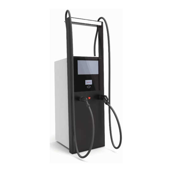
Ingeteam Unit description The charging terminals include isolated DC / DC power converters (called BPM) that adapt the DC main voltage to the needs of the car at all times. 2.2. Main parts of the charging station Ambient LED lighting RFID card reader 21”... - Page 13 Unit description Ingeteam Basic Power Module (BPM) INGEREV RAPID ST chargers incorporate the DC/DC BPM since an external device generates the DC network and the charger only has to adapt the voltage level to the requirements of the car. The BPM DC/DC have two DC/DC converters in parallel.
-
Page 14: Charging Standards
Ingeteam Unit description 2.4. Charging standards The INGEREV RAPID ST family of chargers is compatible with the two available DC charging standards (CCS and CHAdeMO). PP: Proximity Pilot CP: Control Pilot PE: Protective Earth CHAdeMO Charging station side Vehicle side... -
Page 15: Enclosure Opening
Unit description Ingeteam The ST200 chargers include a single power unit (BPM) while the ST400 have two power units. Type and number of connectors Simultaneous charging CHAdeMO INGEREV RAPID ST200 One INGEREV RAPID ST200 Duo INGEREV RAPID ST400 Duo INGEREV RAPID ST400 Duo... -
Page 16: Accessories Fitted As Standard
Ingeteam Unit description To open the front door it is necessary to access two quarter-turn locks from inside the station, accessing these through the side door. Location of access to the two front door unlock latches 2.7. Accessories fitted as standard •... -
Page 17: Optional Accesories
Unit description Ingeteam 2.8. Optional accesories These units can incorporate the following optional accessories: • 3G communication. • Wi-Fi communication. • 21 ”screen with Full HD resolution for commercial purposes. 2.9. Electrical safety Interesting design quantities for electrical safety are disclosed below. -
Page 18: Electrical Diagram Of The Auxiliary Power Supply
Ingeteam Unit description 2.11. Electrical diagram of the auxiliary power supply To supply the auxiliary services of the unit, it is necessary to supply a three-phase 400 V supply (AC) with neutral and protective conductor (PE). The protection elements of the auxiliary systems are described below. -
Page 19: Electrical Diagram Of The Dc Power Circuit
Unit description Ingeteam 16 A 30 mA 230 Vac 4 A 10 A 30 mA Curve C Curve C 230 Vac 6,3 A Ir = 4~6,3 A CHADeMO GENERAL 24 Vdc 12 Vdc 12 Vdc 4 A Water pump 12 Vdc 12 Vdc 12 Vdc Single line of the auxiliary system 2.12. Electrical diagram of the DC power circuit The INGEREV RAPID ST family units are connected to a direct voltage (DC) distribution network. - Page 20 Ingeteam Unit description DC BUSBAR 1x70/2x35 mm 1x70/2x35 mm yellow yellow 2x70 mm 2x70 mm yellow yellow 70 mm KPAR 70 mm yellow yellow KOUT1 KOUT2 120 mm 120 mm yellow yellow XCCS XCHA Single line of the DC power circuit ABX2011IQM01_ - Installation and Operation Manual...
-
Page 21: Specification Table
Unit description Ingeteam 2.13. Specification table INGEREV RAPID ST200 INGEREV RAPID ST400 AC input (auxiliary services) Voltage 380 ~ 440 V Frequency 50/60 Hz Rated current 6 A Rated power 3 kW DC input (power) Voltage 575 ~ 750 V Rated current 300 A 600 A DC output Voltage range 50 ~ 920 V Maximum current 300 A... -
Page 22: Cable Inlets
Ingeteam Unit description 2.14. Cable inlets CAUTION The area for cable access must be sealed with polyurethane foam after installation of the charging station. The wiring necessary for the correct operation of the charging station will be guided inside through the lower opening shaded in the following figure. -
Page 23: Transportation And Handling Of The Unit
IP rating, etc. • Avoid, as far as possible, vibrations which may cause subsequent malfunction. If you observe any anomaly, please contact Ingeteam immediately. Separating the packaging You can deliver all the packaging to an authorized non-hazardous waste management company. - Page 24 Ingeteam Transportation and handling of the unit In order to avoid possible interference with attached components, it is essential to use straight or bow shackles of a maximum size of 1/2 ”. Bow shackle Any handling of the unit must be carried out using the four available lifting points with chains (or textile slings) converging to a single point and with a minimum length of 1.5 m.
-
Page 25: Unit Reception And Storage
Failure to follow the instructions in this section may lead to damage to the unit. Ingeteam accepts no liability for damage resulting from the failure to follow these instructions. If the unit is not installed immediately after reception, the following points should be taken into account in order to avoid damage: •... -
Page 26: Preparation For Installing The Unit
Ingeteam Preparation for installing the unit 5. Preparation for installing the unit When deciding the location of the unit and planning your installation, you must follow a set of guidelines based on the specifications of the unit. These guidelines are summarized in this chapter. - Page 27 Altitude 2000 m The operation of the unit at temperatures greater than 50 ºC should only occur occasionally and not permanently. Ingeteam is not responsible for the consequences to the unit resulting from operating it at temperatures higher than 50 ºC. At altitudes higher than 1000 m, please contact Ingeteam.
-
Page 28: Type Of Grid For The Ac Auxiliary System
Ingeteam Preparation for installing the unit 5.3. Type of grid for the AC auxiliary system Through this connection the necessary energy is supplied to power all the auxiliary components of the unit (refrigeration, control, heating, etc.). These units must be connected to a three-phase star network with grounded neutral. The permissible grounding systems are therefore TT and TN. -
Page 29: External Disconnection System
Preparation for installing the unit Ingeteam 5.4. External disconnection system To inspect the unit, it is necessary to remove the AC supply voltage. For this, the installer must install an external disconnection system. The isolating element must be sized for the DC input voltage and current of the load terminal (see section “2.13. -
Page 30: Installing The Unit
Ingeteam Installing the unit 6. Installing the unit Before installing the unit, the packaging must be removed, taking special care not to damage the housing (see section “4.2. Unpacking”). Check that there is no condensation inside the packaging. If there are signs of condensation, the unit must not be installed until you are sure it is completely dry. - Page 31 Installing the unit Ingeteam You must follow the following stipulations when choosing the place where the unit is to be bolted in: • Minimum distance from the center of the bore to the edge of the concrete pad: 75 mm. •...
- Page 32 Ingeteam Installing the unit Follow these steps: Mark the fixing points on the floor. In case of fixing with screws, drill the ground with a suitable drill bit. If threaded rods are to be used, install these in the ground.
- Page 33 Installing the unit Ingeteam Once the lower plates have been removed, close the front and rear doors to make handling the station safer. The side door will remain open to facilitate the positioning of the station on its anchoring points to the ground.
- Page 34 Ingeteam Installing the unit Install the lower plates, opening the front and rear doors to have better access for fixing the screws and washers. Installation of the bottom plates, simplified view Pass the wiring from the ground into the station through the designated opening.
-
Page 35: Ac Auxiliary Circuit Connection
Respect the polarity of the AC wiring. CAUTION Ingeteam accepts no liability for any damages caused by an incorrect connection. 7.2. Wiring requirements for the AC auxiliary circuit connection CAUTION If using aluminum cables, the installer must provide the necessary means to prevent galvanic coupling (bipolar terminals, bimetallic interfaces, etc.). - Page 36 Ingeteam AC auxiliary circuit connection Using ferrules, connect the three phases, neutral and earth to the terminals marked R, S, T, N and PE, respecting the polarities. R S T N PE R, S, T, N and PE terminals for the connection of the auxiliary system. Access from the side door Check that the connection is secure and that the wiring is not taut.
-
Page 37: Dc Power Circuit Connection
Respect the polarity of the AC wiring. CAUTION Ingeteam accepts no liability for any damages caused by an incorrect connection. 8.2. Wiring requirements for the DC power circuit connection CAUTION If using aluminum cables, the installer must provide the necessary means to prevent galvanic coupling (bipolar terminals, bimetallic interfaces, etc.). -
Page 38: Proceso De Conexión Del Circuito De Potencia Dc
Introduce the wiring through the cable inlets enabled on the bottom of the charger. Connect respecting the polarities indicated in the following figure, using the screws, nuts and washers supplied by Ingeteam. A torque of 50 Nm must be applied (with lubrication). DC power circuit connection In the case of using two conductors per pole, it is essential to place the terminal of each conductor to one side of the plate to guarantee correct electrical contact. -
Page 39: Start-Up
Start-up Ingeteam 9. Start-up Before performing the first energization of the unit, it is necessary to check a series of aspects in order to minimize the consequences of an error during installation or connection. It is convenient to carry out the sequence of checks in the order described below. -
Page 40: Auxiliary Circuit Energization
Ingeteam Start-up 9.3. Auxiliary circuit energization Before introducing external voltage in the auxiliary circuit, make sure that all the protection devices of the auxiliary circuit are tripped. Once the external voltage has been introduced, measure at the FC1 terminals and check (using a multimeter) that the voltages between the phases (400 V), and between phases and neutral (240 V) are correct. - Page 41 Unit disconnection Ingeteam 10. Unit disconnection This section details the procedure to disconnect the charging station. If you want to operate inside the unit, it is mandatory to follow these instructions in the same order in which they appear here to remove tension.
- Page 42 At the end of the unit's life, the waste must be correctly processed by an authorized hazardous waste management company. Ingeteam, in accordance with its policy of respect for the environment, will inform the authorized manager, via this section, of the location of components to be decontaminated.
- Page 43 Waste handling Ingeteam Electrolytic condensers The following highlighted components include electrolytic condensers that need to be processed in accordance with applicable regulations after the end of their useful life. It is fundamentally about the power supplies. Main components with electrolytic condensers...
- Page 44 Ingeteam Waste handling Liquid crystal displays The unit may include several liquid crystal displays that must be processed properly after their useful life. In addition to the two front displays, the insulation monitoring devices incorporate small LCD displays that will need to be processed.
- Page 45 Notes...
- Page 46 Notes...
- Page 47 Ingeteam, S.A. de C.V. Ingeteam SAS Ave. Revolución, nº 643, Local 9 Ingeteam Power Technology India Pvt. Ltd. Le Naurouze B - 140 Rue Carmin Colonia Jardín Español - MONTERREY 2nd floor, 431 31676 Labège - France 64820 - NUEVO LEÓN - México...
- Page 48 ABX2011IQM01_ 01/2021 Ingeteam Power Technology, S.A. www.ingeteam.com...
Need help?
Do you have a question about the INGEREV RAPID ST Series and is the answer not in the manual?
Questions and answers