Table of Contents
Advertisement
Quick Links
Advertisement
Table of Contents

Summary of Contents for Gigabit Sistems MFPR-3100
- Page 1 Multi-format Video Server MFPR-3100 INSTRUCTION MANUAL REV. 1.1...
- Page 2 Safety Precautions To use this product safely, review the following safety precautions. To avoid potential hazards, use this product only as specified. Injury Precautions Use Proper Power Cord To avoid fire hazard, only use the power code specified for this product. Avoid Electric Overload To avoid electric shock or fire hazard, do not apply a voltage to a terminal that is outside the range specified for the terminal.
- Page 3 Product Damage Precautions Use proper power source. Do not operate this product from a power source that applies more than the voltage specified. The specified voltage of this product is within 90-264 VAC, 50-60Hz. Provide Power Ventilation. To prevent product overheating, provide proper ventilation. Prevent Impact Prevent an impact during transportation.
-
Page 4: Table Of Contents
INDEX PREFACE ..............................6 Initial inspection............................6 Outline of the MFPR-3100 ..........................6 Features.................................6 Control of the MFPR-3100..........................7 About recording time .............................7 1. Installations ..............................8 1-1. Confirmation of Environment ......................8 1-2. Assurance of Mains Voltage .......................8 1-3. Connection of Power Cable and Power ON ..................8 1-4. - Page 5 3-4-2. Sequence Playback of Plural Clips ..................35 3-4-3. Clip Export ..........................37 3-5. LOOP Recording .......................... 38 3-6. UP/DOWN Convert of the Output Video ..................39 3-7. Deleting Files ..........................39 4. Remote Control ............................ 40 4-1. Using Remote Desktop Connection ....................40 4-2.UDP Remote Control ........................
-
Page 6: Preface
Power cable Outline of the MFPR-3100 MFPR-3100 is 1-IN 2-OUT (1-Record 2-Playback) configuration. You can control one recording channel and two playback channels independently. It is possible that you can search to the desired position and make instant replay while keeping continuous recording (PLAY while REC feature). -
Page 7: Control Of The Mfpr-3100
Control of the MFPR-3100 MFPR-3100 can be controlled as following control means. (1) GUI application associated with the MFPR-3100. (2) Short cut key from keyboard. (3) Windows Remote Desktop feature. (4) Ethernet UDP protocol. (5) RS-422 Remote control (OPTION) About recording time A total recording time varies according to the SSD capacity, encoding scheme, TV standard and audio channels to be recorded. -
Page 8: Installations
1. Installations Before installation of the MFPR-3100, please read the “Safety Precautions” of this manual. 1-1. Confirmation of Environment This product operates properly within the temperature range of +0-35℃ and the humidity range of 10-90% (Non-condensing). If the temperature of this product is out of this range due to a transportation or preservation, do not power on until the temperature reaches the specified range. -
Page 9: Operation
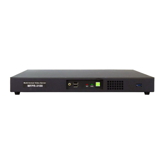
2. OPERATION 2-1. Front Panel Names and functions of the Front Panel switch and LED indicators are as follows: ➂ ➁ ➀ ➄ ➃ ➅ ➀ Power switch This switch turns on or turns off the system. Color of this switch is lit green when the power is ON. -
Page 10: Rear Panel
2-2. REAR PANEL Names and functions of the Rear Panel fans and connectors are as follows: ➀ ➁ ➀ Cooling fan for power supply This fan starts to rotate when connecting the power code on the rear panel and the POWER SWITCH on the front panel is activated. - Page 11 SDI IN input connector BNC receptacle connector for connecting SD/HD-SDI input. OUT-A output connector BNC receptacle connector to output playback SDI signal of OUT-A channel. OUT-B output connector BNC receptacle connector to output playback SDI signal of OUT-B channel. Monitor output connector BNC receptacle connector to output switched monitor SDI output (INPUT, OUT-A, or OUT-B).
-
Page 12: Control With Gui
3. Control with GUI The GUI application utility software is included in the MFPR-3100. This section explains the usage of this utility software. Please connect the PC monitor, mouse and keyboard to the MFPR-3100 if necessary. Another choice is a remote control from external PC, using the Windows REMOTE DESKTOP feature via... -
Page 13: Multi-Format Recorder Gui Names And Functions
3-1. Multi-Format Recorder GUI names and functions ⑧ ⑨ ① ④ ② ⑤ ⑥ ⑦ ③ ① Monitor OUT switcher and status indicator part: Switching the monitor output on the rear panel between INPUT, OUT-A and OUT-B, and showing the current status. ②... -
Page 14: Playback Preview Part Details
3-1-1. Playback Preview part details ⑧ ③ ④ ① ② ⑦ ⑥ ⑤ ⑥ ① VIDEO/AUDIO Monitor: Displays playback video and audio meter. The audio meter channels can be changed in the [Playback settings] menu. ② Slide-bar: Browsing file contents quickly by dragging the button. ③... -
Page 15: Deck Control Part Details
3-1-2. Deck control part details ② ③ ⑦ ① ⑧ ④ ⑤ ⑥ ⑨ ⑪ ⑩ ⑫ ⑬ ⑭ ① GO TO START button: Moves to the start point of the file or clip. ② REWIND button: Runs reverse direction with maximum speed. ③... -
Page 16: Material List Part Details
3-1-3. Material List part details ② ③ ⑤ ④ ① ① Material List: Shows material files those are loaded for playback. It indicates from left, [Thumbnail picture], [File name], [IN point], [OUT point], [Duration], [format], [File path]. You can change the file orders by drag and drop. ②... -
Page 17: Monitor Out Switching And Setting Status Part Details
3-1-4. Monitor OUT Switching and Setting Status part details Monitor Out Switching part: Selects a monitor output that is fed to the MONI OUT connector on the rear panel. There are selections Input, Channel A and Channel B. Setting Status part: Indicates current setting mode. ・... -
Page 18: Recorder Control Part
3-1-5. Recorder control part ④ ① ② ⑤ ③ ⑥ ⑦ ⑧ ① VIDEO and AUDIO Monitor: Displays input video and audio level. The audio meter channels can be changed in the [Capture settings] menu. ② Disk Remain: Indicates the consumed disk space (Green bar) and the remaining disk space (Blank). -
Page 19: Clip Edit Part Details
3-1-6. Clip Edit part details You can make edited clips with desired IN point and OUT point on the selected file. The original material file is not modified, so you can remake the clip many times. ① ③ ④ ⑤ ②... -
Page 20: Clip List Part Details
3-1-7. Clip list part details ② ③ ④ ⑤ ⑥ ⑦ ① ① Clip List: Lists clips made by the Clip Edit part or retrieved from saved clip list. The list indicates [Thumbnail picture]-[Clip name]-[IN point]-[OUT point]-[Duration]-[Format]-[File path]. The mark before IN point shows as follows: ⇒... -
Page 21: Settings Menu
3-1-8. Settings Menu 3-1-8-1 Capture Settings menu You cannot open this menu during record mode. You should stop recording to open this menu. ① ② ③ ④ ⑤ ⑥ ⑦ ⑧ ⑨ ⑩ ⑪ ⑫ ⑬ ⑭ ⑰ ⑯ ⑮ ①... - Page 22 ③ Audio Input Format: Selects an audio input format. ④ Audio input select: This menu is not available. (Embedded audio only.) ⑤ AES/EBU Input level: This menu is not available. ⑥ Video Encode: Selects encoding mode. <<CAUTION>> Do not select the ProRes422 when you use simultaneous REC/PLAY. ⑦...
- Page 23 3-1-8-2 Playback Settings menu (Single file mode) ① ② ③ ④ ⑤ ⑬ ⑥ ⑦ ⑧ ⑨ ⑩ ⑪ ⑭ ⑫ ⑮ ⑯ ① Video Output Format: Selects video format to be output from SDI connector. <<CAUTION>> You should stop the playback for changing the output format. ②...
- Page 24 ③ Audio output level: This menu is not available. (This menu is for the model with AES/EBU audio output.) ④ Input File Loader: If put a check mark on [Enabled] box, all the files in the directory that is designated on the Load Directory window are automatically loaded in the material list when the application is booted.
- Page 25 3-1-8-3 Playback Settings menu(Playlist mode) ① ② ③ On the Control mode ①, If you select the Playlist mode, The ② and the ③ is newly displayed. ② Override Timecode: Selects the timecode count when playback plural clips continuously,. The original Timecode value is used when the check box is empty. The continuous time code from [00:00:00:00] is applied for plural clips when the box is checked.
-
Page 26: Files Menu
3-1-9. Files menu This section explains handlings of files. By clicking the Files menu, the dialog below is displayed. 3-1-9-1. Open from Explorer By clicking this item, the dialog like the Explorer opens. Selects the needed file and clicks OPEN button. - Page 27 3-1-9-5. Loading play list This menu reads out the saved Clip list (or Play list). After clicking, dialog like Explorer opens. Selects the file (The file extension is [.glp]).and click OPEN button. This menu is equivalent to the [Load] button of the Clip list (or Playlist). 3-1-9-6.
-
Page 28: Loading Material Files From The Explorer
3-1-10. Loading Material files from the Explorer When you move the mouse cursor to the bottom of the screen, the taskbar is displayed. By clicking the Explorer icon, the Explorer dialog opens. Open the folder that includes recorded files (the default is D: drive). Select the file you want to load, then Drag and Drop the file to the material list part. -
Page 29: Operating The Simultaneous Record/Play
3-2. Operating the Simultaneous RECORD/PLAY Recording and Playback is controlled independently in this mode. Normally, the playback side playbacks the file being recorded. If you need, you can select different file for playback that was recorded previously. Even in this case, the recording continues till clicking the Stop Recording button. -
Page 30: Start Recording
3-2-2. Start Recording ④ ① ② ⑤ ③ ⑥ ⑦ ⑧ (1) Observe the Recorder control part and check if the video and audio ① and the time code ④ are correctly displayed. (2) Select [Directory] ⑥ for recording and type the [File Name] ⑦ if necessary. (3) Click the [RECORD] button ⑤... -
Page 31: Playback The Other Files
3-2-4. Playback the other files ① Added files Thumbnail picture (1) Newly add material files to the Material list referring to the paragraph 3-1-9 or 3-1-10. (2) Select the [channel selector] ① to choose the playback channel A or B. (3) On the Material list, double click the desirable file to be playback. -
Page 32: Clip Edit
3-3. Clip Edit 3-3-1. Making clips from playback file You can edit and make clips by designating the IN point and OUT point from the playback material file on the Material list. Also, you can change the IN point and OUT point of already determined clips. -
Page 33: Designating In And Out Point From The Recording Timecode
3-3-2. Designating IN and OUT point from the recording timecode You can set the IN point and OUT point from the current time at the recording side. How to set clips (1) Select the [Single file mode] on the [Playback Settings] menu (or push the [F1] key). (2) At the timing that you want to mark as IN point, click the [R Mark In] button ⑥... -
Page 34: Playback Clips
3-4. Playback Clips 3-4-1. Instantaneous Direct Playback (Pong Playback) The clips that registered on the Clip list can be directly played back as the following procedure. (1) Double click one of the clips on the Clip list to enable the play back from the Clip list. (For example, the clip marked ①... -
Page 35: Sequence Playback Of Plural Clips
3-4-2. Sequence Playback of Plural Clips (1) Open the [Setting] menu then click the [Playback settings]. (2) Select [Playlist] at the Control mode. (3) Select the [Off] in the [Pause] check box for continuous sequence playback. If you want to stop playback at each clip, select [Pause Next] (waiting the next play command at the beginning of the next clip) or [Pause End] (Waiting the next play command at the end of the current clip). - Page 36 (7) Double click on the clip that you want to start. (8) Click the [PLAY] button or push the [Space] key to start the sequence playback. Starting clip Registered clips <CAUTION> The sequence playback will not be smooth when you use the clips from low speed external devices.
-
Page 37: Clip Export
3-4-3. Clip Export You can export the selected clip to internal or external drives. (1) Select the clip by clicking the Clip on the clip list. (2) Click the [Clip Export] button. (3) A dialog like Explorer opens. Choose the directory and put the file name, then click the [Save] button. -
Page 38: Loop Recording
3-5. LOOP Recording You can make an endless recording by using the LOOP Recording mode. (1) Open the [Settings] menu and select the [Capture settings] (2) Check the [Loop] check box. The [File name] mode changes to the [Date+Time] and the [Capture timecode] mode changes to the [PC Time] automatically. -
Page 39: Up/Down Convert Of The Output Video
3-6. UP/DOWN Convert of the Output Video You can change the video format on the video output. (1) Confirms that the Deck mode is in stop. Open the [Settings] mode and select the [Playback settings]. (2) Click the Tab at the [Video Output Format] to observe the output TV standards. (3) Select the TV standard that you want to output. -
Page 40: Remote Control
<CAUTION> To terminate the [Remote Desktop Connection], You must execute the following procedure. (1) Change the size of GUI on the Host (MFPR-3100) to smaller size and observe the Desktop. (2) Click the [rdtexit] icon on the top left of the Desktop, then right-click this icon. -
Page 41: Udp Remote Control
4-2-1. Outline MFPR-3100 can be remotely controlled by the Ethernet UDP protocol. The MFPR-3100 UDP protocol uses the SONY RS-422 compatible [VTR control protocol] and dedicated [Disk control protocol] that is extended to control our Disk Recorders. 4-2-2. Structure of communication data The data format is that the commands and the status are described on the payload in the Ethernet UDP packets.フ... -
Page 42: Disk Control Protocol Command Format
1/DATA COUNT to the last data word before the checksum. 4-2-5. Disk Control Protocol Command Format MFPR-3100 provides dedicated protocol for the disk recorder control. The extended disc control command format is described as follows. It consists of the Extend code (0x3E), Data length, CMD 1, CMD 2, DATA and CHECKSUM. -
Page 43: Communication Protocol
4-2-6. Communication Protocol When the recorder receives a command from the control system, it sends back the following return telegram. ・ If the recorder receives a command without data request: ACK (10h, 01h) = Acknowledgement of receipt. ・ If the Recorder receives a command with data request: Answer code + data ・... -
Page 44: Command List
4-2-7. Command List The typical command and status of the UDP control is as follows. Please refer to the separate UDP Protocol Manual for more detailed protocol description. ・VTR control protocol commands CODE Command Data Response 10 01 11 12 NACK ・拡張ディスク制御プロトコルコマンド... -
Page 45: Rs-422 Remote Controller (Option)
4-3. RS-422 Remote Controller (OPTION) 4-3-1. Outline MFPR-3100 has two D-SUB 9-pin female connectors on the rear panel that conforms to EIA RS-422 Serial Remote Control Protocol. Most of controllers with the same control protocol can remotely control this product. - Page 46 4-3-2. Pin assignment of the connectors The pin assignment of the D-SUB 9-pin female connector is shown below: Pin number Signal TX-A RX-B TX-B D-SUB 9-pin RX-A Female The A and B is defined as follows:...
-
Page 47: Architecture Of The Serial Transmission Data
4-3-3. Architecture of the serial transmission data ・ 4-wire-transmission system. ・ Asynchronous bit-serial word-serial data transmission. ・ Data structure: 1 Start bit+8 Data bits+1 Parity bit+1 Stop bit Mark Start Parity (LSB) (MSB) (Odd) Space (Note 1) Odd Parity: The sum of the D0+D1+---D7 and Parity bit is an odd number. (Note 2) Mark B>A;... - Page 48 ・ Data count: Defines the number of data words that are inserted after CMD2 (0x0-0xF). ・ CMD 2: Is the specific command to the recorder or the command return message from the recorder, respectively. ・ DATA: The number of data words and their contents are defined by the CMD2 command. ・...
-
Page 49: Communication Protocol
4-3-5. Communication Protocol When the recorder receives a command from the control system, it sends back the following return telegram. ・ If the recorder receives a command without data request: ACK (10h, 01h) = Acknowledgement of receipt. ・ If the Recorder receives a command with data request: Answer code + data ・... -
Page 50: Rs-422A Command List
4-3-6. RS-422A Command List CODE Recorder command Meaning Response Footnote 00 11 DEVICE TYPE REQUEST Machine ID 12 11 XX YY 20 00 STOP 10 01 (ACK) 20 01 PLAY 10 01 20 02 RECORD Crash-Record 10 01 20 04 STANDBY OFF 10 01 20 05... - Page 51 44 05 USER BIT PRESET 10 01 *12) 40 10 IN ENTRY Mark as IN point 10 01 40 11 OUT ENTRY Mark as OUT point 10 01 44 14 IN DATA PRESET Set IN point 10 01 *6) *9) 44 15 OUT DATA PRESET Set OUT point...
- Page 52 Footnote *0) xx=data-1, yy=data-2. Default: data-1=00, data-2=E0 *1) The slow-motion speed range is 0±3 times PLAY speed. *2) The low-resolution speed data consists of one byte (Value=0-255). The real speed in multiplies of play is defined as: ( ) Value/32-2 Real speed=10 This means the speed data is the logarithmic of the Real speed.
- Page 53 *13) The high-resolution EDIT PRESET is the bit transparent representation of record mode and the track selection Data 1: Bit0 Not used Bit4 Video track Bit1 Not used Bit5 Assemble mode Bit2 Time-code track Bit6 Insert mode Bit3 Not used Bit7 Not used Data 2:...
- Page 54 Data Definition Response Request Time code 74h, 04h, 4 bytes BCD Time code Request User bit 74h, 15h, 4 bytes User bit Request Time code + 11h, 78h, 04h, 8 bytes BCD Time code + User bit User bit *20) There is a field-ID in the time code data: 60Hz/DATA2 50Hz/DATA4 Field...
- Page 55 *22) The STATUS SENSE data is defined as: ・ High nibble (Bit4-7): the first data byte number of status field. ・ Low nibble (Bit0-3): number of data bytes out of status field. ・ Response: 7xh, 20h, and x data bytes of status field is: Data byte Status Status...
-
Page 56: 5.Maintenance
5.Maintenance 5-1 Cleaning of the Air Intake and vent If the air intake on the front panel and exhaust port on the rear panel gather dust, internal temperature increases resulting malfunctions and failure. Please make a cleaning. (1) Clean with a vacuum cleaner at the air intake below. Air Intake part Clean with a vacuum cleaner at the air exhaust port below. -
Page 57: Appendix Shortcut Key Assignment
Appendix Shortcut Key Assignment By pressing the following keyboard key, you can control the GUI quickly. In case of entering the names and comments, the keys work as normal character keys. Tab key Moves selection of buttons and windows. Enter key Fixes the selected items. - Page 58 Ctrl+3 key Reverse x 3/4 speed Ctrl+4 key Reverse x 1 speed Ctrl+5 key Reverse x 2 speed Ctrl+6 key Reverse x 4 speed Ctrl+7 key Reverse x 10 speed Ctrl+8 key Reverse x 20 speed Ctrl+9 key Reverse x 40 speed Clip Reset Clip Add/Set Rewind...
Need help?
Do you have a question about the MFPR-3100 and is the answer not in the manual?
Questions and answers