Table of Contents
Advertisement
Quick Links
Advertisement
Table of Contents

Related Manuals for Clockaudio CCRM 4000

Summary of Contents for Clockaudio CCRM 4000
- Page 1 Installation and User Guide CCRM 4000 (Motorised, Ceiling Retractable Microphone)
- Page 3 Thank you for purchasing a Clockaudio product. We are confident that this product will give you many years of trouble free operation. As part of Clockaudio’s continual ongoing programme of product development, improvements to the existing CCRM 4000 microphone range may be made to further increase the already excellent reliability and functionality.
- Page 4 Equipment covered by this User Guide. This User Guide covers all versions of CCRM 4000 product set. The product is specifically designed for use in AV conference rooms, board rooms, court rooms, and huddle room applications or meeting room spaces.
-
Page 5: Table Of Contents
Contents Overview ............................1 Package Contents ..........................3 Installation ............................4 Single Element version of CCRM 4000 ..................4 Tri Element version of CCRM 4000 ..................8 IR Sensor Installation ......................11 Secondary unit wiring connections ..................11 Further Secondary wiring connection ................... 12 Horizontal / Vertical mounting ..................... - Page 6 Page iv of iv V2.1 2021-01...
-
Page 7: Overview
1 Overview The CCRM 4000 product is designed for use in AV conference rooms, board rooms, court rooms, and huddle room applications or meeting room spaces. Typically mounted in the ceiling space, it allows the microphone to be released smoothly from the unit and drop down to a predefined height and when not in use to smoothly retract back into the ceiling. - Page 8 The CCRM 4000 is available with either a single element (C3) or a tri element (C303) microphone. Both microphones, available in either black or white finish, provide an excellent pickup and proven audio quality. Definition of whether the product appears as a Main or Secondary device is defined by the settings on the two rotary decimal encoders.
-
Page 9: Package Contents
2 Package Contents The following part are supplied with each of the product types CCRM 4000 Type CCRM 4000 unit Single element microphone ... -
Page 10: Installation
Do not remove the microphone and top bezel assembly at this stage. Remove the small cardboard box located under the CCRM 4000. This contains the PSU (Main unit only). Page 4 of 25 V2.1 2021-01... - Page 11 76mm (3") from the edge of the tile or it will not be possible to align the CCRM 4000 support bracket over the hole. Take the entire CCRM 4000 kit up to the final location site. Carefully align the CCRM 4000 complete with ceiling tile bracket so that the...
- Page 12 (2 at each end of the bracket) are used to secure the frame and also used to suspend the CCRM 4000 and bracket. Unravel the Y cable harnesses and attach the hooks to the eye bolts at each end of the ceiling tile bracket.
- Page 13 DSP. The unit can now be operated normally. Should this fail to restore normal operation disconnect and reconnect the supply Voltage to the CCRM 4000. V2.1 2021-01 Page 7 of 25...
-
Page 14: Tri Element Version Of Ccrm 4000
Cut the tape securing the large cardboard box to the large black ceiling frame. Remove the small cardboard box located under the CCRM 4000. This contains the PSU (Main unit only). Now open the large cardboard box and remove Safety... - Page 15 76mm (3") from the edge of the tile or it will not be possible to align the CCRM 4000 support bracket over the hole. Take the entire CCRM 4000 kit up to the final location site. Carefully align the CCRM 4000 complete with ceiling tile bracket so that the...
- Page 16 Connect the microphone on to the Mini XLR connector (push fit). WARNING: Do not operate the CCRM 4000 without connecting the microphone. Remove any kinks or bends in the cable by gripping the cable with your hands and pass it through a clean dry cloth a few times.
-
Page 17: Ir Sensor Installation
Drill a 16mm (5/8") diameter hole. Pass the sensor through the hole and secure it using the C clip. Connect the cable to the IR sensor input Socket 1 (IR) on the CCRM 4000 unit. IR sensor has 2 coloured LED’s: Green illumination while in programme mode and Red during normal operation. -
Page 18: Further Secondary Wiring Connection
Important: When using a DSP to control the system ensure that the DSP control signal is already outputting +V to Socket 3 (DSP IN) on the CCRM 4000 Main unit (+2.5 to 12 Volts) before powering the system up. Otherwise the DSP command will not be recognised by the system and unit will fail to operate. -
Page 19: Horizontal / Vertical Mounting
Horizontal / Vertical mounting Apart from mounting the CCRM 4000 units in the ceiling space, these units can also be mounted on a wall or a bracket attached to the ceiling. In either case a secure bezel attachment, where the microphone emanates from, will need to be addressed by the installer. -
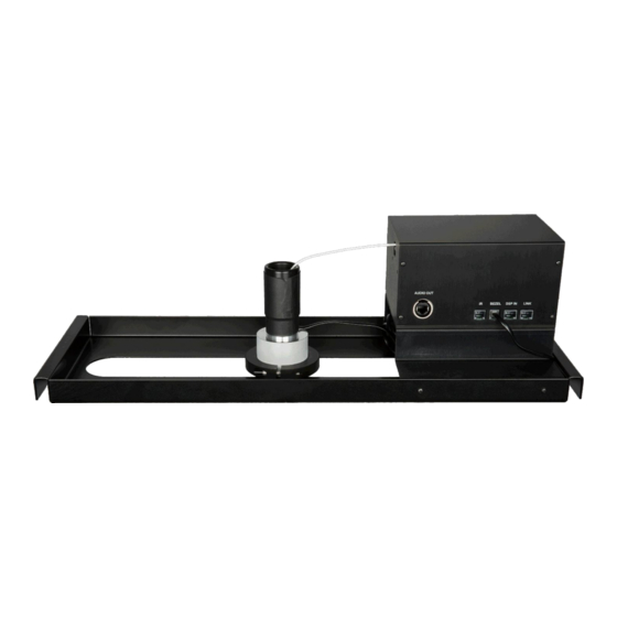
Page 20: Controls And Connectors
4 Controls and Connectors On both sides of the CCRM 4000 there are controls and connectors. Description Connector Power Two +18VDC power connectors are provided. One can be used for power In, while the other can be used to distribute power to the next daisy chained unit. - Page 21 Secondary units need to be setup with a number that is non-zero. All Secondary units MUST have unique ID numbers. On the other side of the CCRM 4000, there are additional connectors Description Connector Single element CCRM 4000 provides audio out via a...
-
Page 22: Connecting To Dsp
Connect Socket 3 (DSP IN) to the DSP. Ensure that all parameters are met in accordance to the instructions shown under “Mute Control” and Logic Hi /Lo 2.5V – 12V required for activation is available. This cable provides muting info to DSP and receives trigger to deploy CCRM 4000. Page 16 of 25... -
Page 23: Dsp Mute Control
Connect the microphone audio output to DSP audio input. Phantom power must be supplied to the microphone. For tri element CCRM 4000 use the link cable. DSP is used to mute the microphone. DSP Mute Control Each CCRM 4000 provides its mute status via Socket 3’s optically isolated open-collector output. The Secondary units cascade their status into the Main’s Socket 4. -
Page 24: Audio Out Socket
Audio Out Socket The type of socket on the Audio out is dependent upon the type of CCRM 4000 that was purchased. Single Element version 5.4.1 On the single element CCRM 4000 audio output is provided via a 3 pin XLR connector for connection to a mixer of DSP. -
Page 25: Programming Ccrm Cable Height
The remote is primarily intended to allow the initial programming of the desired height for each individual CCRM 4000 in the system. The preferred operation is then by logic input from a DSP logic high of 2.5V to 12V to trigger release of the microphone to the programmed height; logic 0 low will raise the microphone. -
Page 26: Ir Remote Control Additional Information
IR Remote Control Additional Information When programming an incorrect address ID code, for example 32, and that address ID does not exist, it will just be ignored / nothing will happen when either the up-arrow or down- arrow keys are pressed. Wait 5 seconds and re-enter the correct address code. While initially programming the cable height, the Up and Down buttons work on a press and ... -
Page 27: Programming Cable Height On Secondary Unit
DSP to retract or deploy the microphone. The unit can now be operated normally. Should this fail to restore normal operation disconnect and reconnect the supply Voltage to the CCRM 4000. V2.1 2021-01... -
Page 28: Troubleshooting
Main unit. Check that the correct address code (if adjusting height) for the CCRM 4000 has been input. Cautions 1. Never grab hold of or stop the cable whilst the cable is being deployed. This may cause jamming of the mechanism of the cable. -
Page 29: Specifications
8 Specifications Single Element CCRM 4000 Tri Element CCRM 4000 Polar pattern Cardioid Cardioid (120 degrees coverage) (360 degrees coverage with all three (each capsule) capsules activated) Frequency response 50Hz – 18KHz Sensitivity -40dB +/-3dB at 1KHz (0dB=1 V/Pa) -37dB @ 1KHz (0dB 1v/Pa) -
Page 30: Product Warranty
The warranty does not cover accidental damage, misuse, cabinet parts, knobs, batteries or consumable items. Any product returned to Clockaudio failing to meet the terms listed will incur a repair and carriage charge. The product must be correctly installed and operated in accordance with the instructions ... -
Page 31: Product Disposal
10 Product Disposal At the end of the life of this equipment, dispose of equipment according to local regulations For more information and advice on Clockaudio products please visit the Clockaudio website: www.clockaudio.com Corporate Headquarters: Clockaudio Limited, Wellington Gate, Silverthorne Way,...
Need help?
Do you have a question about the CCRM 4000 and is the answer not in the manual?
Questions and answers