Table of Contents
Advertisement
Available languages
Available languages
Quick Links
READ AND SAVE THESE INSTRUCTIONS
BUILDER Series
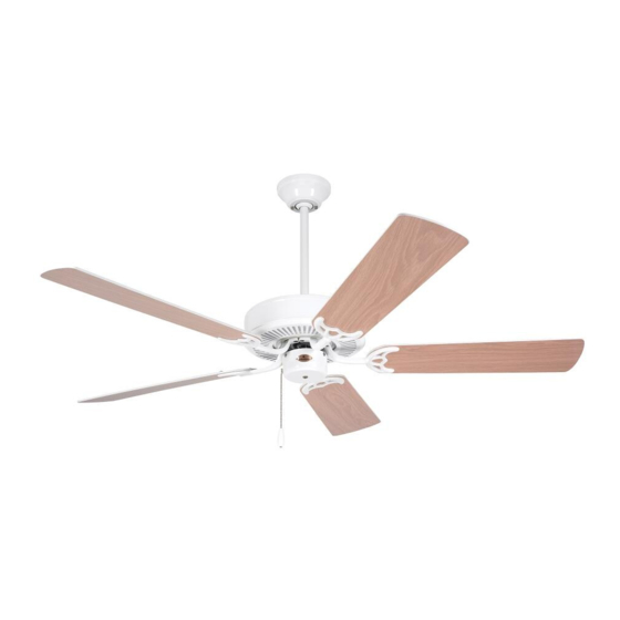
52" Ceiling Fan Owner's Manual
CF700BS09
CF700ORB09
CF700WW09
Questions, problems, missing parts: Before returning to the store, Call Customer Service
Part No. F40BP73120006
Revision: 02152021
Model Numbers
- Brushed Steel
- Oil Rubbed Bronze
- Appliance White
14.4
Net Weight:
1-800-777-4440
Lbs.
• Español - página 25
• Français - page 49
Form No. BP7312-6
U.L. Model No.: 52-ANT
Advertisement
Chapters
Table of Contents

Subscribe to Our Youtube Channel
Related Manuals for Kathy Ireland PRO Series


Summary of Contents for Kathy Ireland PRO Series
- Page 1 READ AND SAVE THESE INSTRUCTIONS BUILDER Series 52” Ceiling Fan Owner’s Manual Model Numbers CF700BS09 - Brushed Steel CF700ORB09 - Oil Rubbed Bronze CF700WW09 - Appliance White 14.4 Net Weight: Lbs. Questions, problems, missing parts: Before returning to the store, Call Customer Service 1-800-777-4440 •...
-
Page 2: Table Of Contents
Table of Contents Section Page Section Page Safety Instructions . . . . . . . . . . . . . . . . . . . . . . . . . . . 2 8 . -
Page 3: Unpacking Instructions
1. Unpacking Instructions PACKAGE CONTENTS WARNING Do not install or use fan if any part is damaged or Part Description Quantity missing. Call Toll-Free for replacement parts: Fan Motor Assembly 1-800-777-4440 Ceiling Cover Switch Housing Assembly WARNING Hanger Bracket This product is designed to use only those parts supplied with this product and/or any accessories Hanger Ball/4.5”... -
Page 4: Electrical Requirements
1. Unpacking Instructions (Continued) This Manual Is Designed to Make it as Easy as Possible for You to Assemble, Install, Operate and Maintain Your Ceiling Fan Tools Needed for Assembly WARNING One Phillips head screwdriver One stepladder Before assembling your ceiling fan, refer to section One Standard screwdriver One wire stripper on proper method of wiring your fan (page 13). -
Page 5: Ceiling Fan Assembly
3. Ceiling Fan Assembly WARNING Disconnect Electrical Power to the Branch Circuit at Turning off wall switch is not sufficient. To avoid the Circuit Breaker Panel or Main Fuse Box before possible electrical shock, be sure electricity is turned attempting to install the Ceiling Fan to the Outlet Box . off at the main fuse box or circuit breaker panel before wiring. - Page 6 3. Ceiling Fan Assembly (Continued) DOWNROD HAIRPIN Loosen the Two Set Screws in the Motor Coupler . CLIP CLEVIS Place the Hanger Ball/4 .5” Downrod Assembly into the Motor Coupler, aligning the Clevis Pin Holes in the Downrod with the Holes in the Motor Coupler CLEVIS HAIRPIN (Figure 3) .
- Page 7 3. Ceiling Fan Assembly (Continued) The Fan comes with Blue, Black and White Wires that are 42” long . 6 to 9 INCHES Measure up approximately 6 to 9-inches above top of Hanger Ball/4 .5” Downrod Assembly (Figure 5) . Cut off excess Wires and strip back insulation 1/2-inch HANGER BALL/ from end of Wires .
- Page 8 3. Ceiling Fan Assembly (Continued) M5 x 6 mm WASHER Mount the Blade Flange to the Fan Blade using Three HEAD SCREW (3) M5 x 6mm Washer Head Screws (supplied) (Figure 8) . Repeat this procedure for other Four Fan Blades and FAN BLADE Blade Flanges .
- Page 9 3. Ceiling Fan Assembly (Continued) 3.11 SWITCH HOUSING Remove the Three Switch Housing Mounting Screws MOUNTING PLATE (Figure 10) from the Switch Housing Plate . Retain the Screws for future use in Step 3 .13 . NOTE: If you are using an Luminance Brands light fixture with your fan.
- Page 10 3. Ceiling Fan Assembly (Continued) 3.13 Position the Switch Housing Assembly on the Switch Housing Plate and align the Holes in the Switch SWITCH Housing Assembly with the Holes in the Plate . HOUSING ASSEMBLY Secure the Switch Housing Assembly by reinstalling the three Mounting Screws (previously removed) (Figure 12) .
-
Page 11: How To Hang Your Ceiling Fan
4. How to Hang Your Ceiling Fan CAUTION CEILING To reduce the risk of injury, install the fan so that the blades are at least 7 ft. (2.1m) above the floor (Figure 13). AT LEAST FLOOR Figure 13 WARNING The outlet box and joist must be securely mounted and capable of supporting at least 50 lbs. - Page 12 4. How to Hang Your Ceiling Fan (Continued) NOTE: SUPPLY WIRES AND FAN WIRES OMITTED FOR CLARITY. Carefully lift the Fan and seat the Hanger Ball/ Downrod Assembly on the Hanger Bracket that was just attached to the Outlet Box (Figure 15) . Be sure the OUTLET Groove in the Ball is engaged with the Anti-Rotation Tab on the Hanger Bracket (Figure 15) .
-
Page 13: How To Wire Your Ceiling Fan
5. How to Wire Your Ceiling Fan If you feel that you do not have enough electrical wiring knowledge or experience, have your fan installed by a licensed electrician. GROUND CONDUCTOR SUPPLY WARNING To avoid possible electrical shock, be sure electricity is turned off at the main fuse box or circuit breaker panel before wiring. - Page 14 5. How to Wire Your Ceiling Fan (Continued) Securely connect the Fan Motor Black Wire and Blue Wire to the Supply Black (hot) Wire using Wire FAN MOTOR Connector (supplied) (Figure 18) . BLACK WIRE SUPPLY BLACK (HOT) LISTED WIRE CONNECTOR FAN MOTOR BLUE WIRE...
-
Page 15: Final Assembly
6. Final Assembly Screw the Two Threaded Studs (supplied) into the Tapped Holes in the Hanger Bracket (Figure 20) . THREADED STUDS (2) Figure 20 Lift the Ceiling Cover up to the Threaded Studs and turn until Studs protrude through the Holes in the CEILING COVER Ceiling Cover (Figure 21) . -
Page 16: Using Your Ceiling Fan
7. Using Your Ceiling Fan Restore Electrical Power to the Outlet Box by turning the Electricity on at the Main Fuse Box or Circuit Breaker Panel . During Summer Months, run the Fan Counter- Clockwise, as you look up at it, to direct airflow downward . -
Page 17: Maintenance
8. Maintenance IMPORTANT CARE INSTRUCTIONS WARNING for your Ceiling Fan Do not use water when cleaning your ceiling fan. Periodic cleaning of your new ceiling fan is the only It could damage the motor or the blades and create the maintenance that is needed . -
Page 18: Repair Parts
10. Repair Parts PARTS BAG U.L. Model No.: 52-ANT... - Page 19 10. Repair Parts Listing Part Numbers Model No. Model No. Model No. Description CF700BS09 CF700ORB09 CF700WW09 Hanger Ball Assembly, Consisting of: 760750-24 760750-48 760750-3 Hanger Bracket (1) — — — Hanger Ball (1) — — — 4.5” Downrod (1) — —...
-
Page 20: Troubleshooting
11. Troubleshooting WARNING FOR YOUR OWN SAFETY TURN OFF POWER AT MAIN FUSE BOX OR CIRCUIT BREAKER PANEL BEFORE TROUBLESHOOTING YOUR FAN. TROUBLE PROBABLE CAUSE SUGGESTED REMEDY 1. Fan will not start. 1 . Reversing switch in neutral position . 1 . -
Page 21: Energy Efficient Use Of Ceiling Fans
12. Energy Efficient Use of Ceiling Fans Using the Ceiling Fan Year Round. In the summer, Ceiling fan performance and energy savings rely heavily on the proper installation and use of the use the ceiling fan in the counter-clockwise direction . ceiling fan . - Page 22 Notes U.L. Model No.: 52-ANT...
-
Page 23: Ceiling Fan Limited Warranty
Luminance Brands Ceiling Fan Product Limited Warranty What The Limited Warranty Covers: This limited warranty is offered by Luminance Brands (“Luminance Brands” or “our” or “we” or “us”) to the original purchaser (“you” or “your”) of a consumer or industrial Luminance Brands ceiling fan product including its motor and the other components, and accessories of a consumer or industrial Luminance Brands ceiling fan product sold separately (“Luminance Brands Ceiling Fan Product(s)”) against defects in workmanship and materials, subject to the exclusions described below. - Page 24 SERIAL NUMBER: DATE CODE: The serial number of this fan can be found on the nameplate on top of the fan housing . The date code can be found on the carton and on top of the fan housing, stamped in ink on a white label . You should record this data above and keep it in a safe place for future use .
-
Page 25: Spanish
LEA Y GUARDE ESTAS INSTRUCCIONES Serie BUILDER Manual del usuario para ventiladores de techo de 52 pulgadas Números de modelo CF700BS09 - Acero cepillado CF700ORB09 - Bronce aceitado CF700WW09 - Blanco electrodoméstico 14,4 Peso neto: Preguntas, problemas, piezas faltantes: Antes de devolver el producto a la tienda, llamar a servicio al cliente 1-800-777-4440 •... - Page 26 Índice Sección Página Sección Página Instrucciones de seguridad ....... 26 7.
- Page 27 1. Instrucciones de desempaquetado CONTENIDO DEL PAQUETE ADVERTENCIA No instale ni utilice el ventilador si cualquier pieza está dañada Pieza Descripción Cantidad o falta. Llame gratis para obtener piezas de repuesto: Ensamblaje del motor del ventilador 1-800-777-4440 Cubierta del techo Ensamblaje de la carcasa del interruptor ADVERTENCIA Soporte de suspensión...
- Page 28 1. Instrucciones de desempaquetado (continuación) Este manual está diseñado para que usted pueda ensamblar, instalar, utilizar y mantener su ventilador de techo de la manera más fácil posible Herramientas necesarias ADVERTENCIA para el ensamblaje Antes de ensamblar su ventilador de techo, consulte la Un destornillador de cabeza Phillips Una escalera de mano sección sobre el método apropiado para cablear el ventilador...
- Page 29 3. Ensamblaje del ventilador de techo ADVERTENCIA Desconecte la alimentación eléctrica al circuito derivado en el No basta con poner el interruptor de pared en la posición de panel de cortacircuitos o la caja de fusibles principal antes de apagado. Para evitar una posible descarga eléctrica, asegúrese intentar instalar el ventilador de techo en la caja de tomacorriente.
- Page 30 3. Ensamblaje del ventilador de techo (continuación) VARILLA DOWNROD HAIRPIN CLIP DE DESCENDENTE CLIP Afloje los dos tornillos de ajuste ubicados en el acoplamiento del HORQUILLA CLEVIS PASADOR DE motor. HORQUILLA Coloque el ensamblaje de esfera de suspensión/varilla descen- dente de 4,5 pulgadas en el interior del acoplamiento del motor, PASADOR DE CLEVIS alineando los agujeros para pasador de horquilla ubicados en la...
- Page 31 3. Ensamblaje del ventilador de techo (continuación) El ventilador viene con cables de conexión de color azul, negro y blanco que tienen 42 pulgadas de longitud. 6 to 9 6 a 9 PULG. INCHES Mida hacia arriba aproximadamente de 6 a 9 pulgadas por encima de la parte superior del ensamblaje de esfera de suspensión/varilla descendente de 4,5 pulgadas (Figura 5).
- Page 32 3. Ensamblaje del ventilador de techo (continuación) TORNILLO PARA PALETA CON CABEZA M5 x 6 mm WASHER DE ARANDELA M5 x 6 mm (3) HEAD SCREW (3) Monte la pestaña para paleta en la paleta del ventilador utilizando tres tornillos con cabeza de arandela M5 x 6 mm FAN BLADE PALETA DEL VENTILADOR (suministrados) (Figura 8).
- Page 33 3. Ensamblaje del ventilador de techo (continuación) 3.11 PLATO DE MONTAJE SWITCH HOUSING DE LA CARCASA DEL Retire los tres tornillos de montaje de la carcasa del MOUNTING PLATE INTERRUPTOR interruptor (Figura 10) del plato de la carcasa del interruptor. Retenga los tornillos para uso futuro en el Paso 3.13.
- Page 34 3. Ensamblaje del ventilador de techo (continuación) 3.13 Posicione el ensamblaje de la carcasa del interruptor sobre el ENSAMBLAJE plato de cubierta de la carcasa del interruptor y alinee los agujeros SWITCH DE LA CARCASA ubicados en el ensamblaje de la carcasa del interruptor con los HOUSING DEL INTERRUPTOR ASSEMBLY...
- Page 35 4. Cómo colgar su ventilador de techo PRECAUCIÓN CEILING TECHO Para reducir el riesgo de lesiones, instale el ventilador de manera que las paletas estén al menos a 7 pies (2.1 m) de altura sobre el piso (Figura 13). POR LO AT LEAST MENOS 7 PIES FLOOR...
- Page 36 4. Cómo colgar su ventilador de techo (continuación) NOTA: LOS CABLES DE SUMINISTRO Y LOS CABLES DEL VENTILADOR NOTE: SUPPLY WIRES AND FAN WIRES OMITTED FOR CLARITY. SE HAN OMITIDO PARA MAYOR CLARIDAD. Levante cuidadosamente el ventilador y asiente el ensamblaje de esfera de suspensión/varilla descendente en el interior del soporte de suspensión que se acaba de acoplar a la caja de CAJA DE...
- Page 37 5. Cómo colgar su ventilador de techo Si le parece que no tiene suficientes conocimientos o experiencia en cableado eléctrico, haga que un electricista con licencia instale su ventilador. CABLE DE SUMINISTRO DEL GROUND CONDUCTOR DE CONEXIÓN ADVERTENCIA CONDUCTOR SUPPLY A TIERRA Para evitar una posible descarga eléctrica, asegúrese de que la electricidad esté...
- Page 38 5. Cómo colgar su ventilador de techo (continuación) Conecte de manera segura el cable negro y los cables azules del motor del ventilador al cable negro de suministro (con corriente) CABLE NEGRO FAN MOTOR DEL MOTOR DEL utilizando el conector de cables suministrado (Figura 18). BLACK WIRE VENTILADOR SUPPLY...
- Page 39 6. Ensamblaje final Enrosque los dos espárragos roscados (suministrados) en los agujeros roscados del soporte de suspensión (Figura 20). ESPÁRRAGOS THREADED ROSCADOS (2) STUDS (2) Figura 20 Levante la cubierta del techo hasta los espárragos roscados y gírela hasta que dichos espárragos sobresalgan a través de los CEILING COVER agujeros ubicados en la cubierta del techo (Figura 21).
- Page 40 7. Utilización del ventilador de techo Restablezca la alimentación eléctrica a la caja de tomacorriente conectando la electricidad en la caja de fusibles principal o el panel de cortacircuitos. Durante los meses de verano, utilice el ventilador de manera que rote en sentido contrario al de las agujas del reloj, según mira hacia arriba al ventilador, para dirigir hacia abajo la circulación de aire.
- Page 41 8. Mantenimiento INSTRUCCIONES DE CUIDADO IMPORTANTES ADVERTENCIA para su ventilador de techo No use agua cuando limpie su ventilador de techo. El agua La limpieza periódica de su nuevo ventilador de techo es el podría dañar el motor o las paletas y crear la posibilidad de una único mantenimiento que se necesita.
- Page 42 10. Piezas de repuesto PARTS BAG BOLSA DE PIEZAS No. de modelo U.L.: 52-ANT...
- Page 43 10. Lista de piezas de repuesto Números de pieza Número de modelo Número de modelo Número de modelo de clave Descripción CF700BS09 CF700ORB09 CF700WW09 Ensamblaje de la esfera 760750-24 760750-48 760750-3 de suspensión, que consiste en: Soporte de suspensión (1) —...
- Page 44 11. Resolución de problemas ADVERTENCIA POR SU PROPIA SEGURIDAD, DESCONECTE LA ALIMENTACIÓN ELÉCTRICA EN LA CAJA DE FUSIBLES PRINCIPAL O EL PANEL DE CORTACIRCUITOS ANTES DE SOLUCIONAR PROBLEMAS DE SU VENTILADOR. PROBLEMA CAUSA PROBABLE REMEDIO SUGERIDO 1. Interruptor de inversión en posición neutral. 1.
- Page 45 12. Uso energéticamente eficiente de los ventiladores de techo El rendimiento del ventilador de techo y el ahorro de energía se Utilización del ventilador todo el año. En verano, use el basan fundamentalmente en su instalación y uso correctos. A ventilador de techo de manera que gire en sentido contrario al continuación se dan unos consejos para asegurar la calidad y el de las agujas del reloj.
- Page 46 Notas No. de modelo U.L.: 52-ANT...
- Page 47 Garantía limitada para productos de ventilador de techo Luminance Brands Lo que la garantía limitada cubre: Esta garantía limitada es ofrecida por Luminance Brands (“Luminance Brands” o “nuestro” o “nuestra” o “nuestros” o “nuestras” o “nosotros”), al comprador original (“usted” o “su”) de un producto de ventilador de techo Luminance Brands de consumo o industrial, incluyendo su motor y los demás componentes, así...
- Page 48 NÚMERO DE SERIE:____________________________________ CÓDIGO DE FECHA:__________________________________ El número de serie de este ventilador se puede encontrar en la placa de especificaciones ubicada encima de la carcasa del ventilador. El código de fecha se puede encontrar en la caja de cartón y encima de la carcasa del ventilador, estampado en tinta en una etiqueta blanca.
-
Page 49: French
LISEZ ET CONSERVEZ CES INSTRUCTIONS Série BUILDER Mode d’emploi du ventilateur de plafond de 52 po Numéros des modèles CF700BS09 - Acier brossé CF700ORB09 - Bronze huilé CF700WW09 - Blanc électroménager 14,4 Poids net : Questions, problèmes, pièces manquantes : Avant de retourner un produit au magasin, téléphoner le service à... -
Page 50: Consignes De Sécurité
Table des matières Section Page Section Page Consignes de sécurité ........50 7. -
Page 51: Instructions Pour Le Déballage
1. Instructions pour le déballage CONTENU DU PAQUET AVERTISSEMENT Il ne faut pas installer le ventilateur si une pièce quelconque est Pièce Description Quantité endommagée ou manquante. Ensemble de moteur de ventilateur +1-800-777-4440 Monture de plafond Ensemble de boîtier d’interrupteur AVERTISSEMENT Support de suspension Ensemble de tige de suspension... -
Page 52: Alimentation Électrique
1. Instructions pour le déballage (suite) Ce mode d’emploi est conçu pour vous permettre d’assembler, d’installer, d’utiliser et d’entretenir votre ventilateur de plafond aussi facilement que possible Outils nécessaires pour le montage AVERTISSEMENT Un tournevis à pointe cruciforme Un escabeau Avant d’assembler votre ventilateur de plafond, référez-vous à... -
Page 53: Assemblage Du Ventilateur De Plafond
3. Assemblage du ventilateur de plafond AVERTISSEMENT Déconnectez l’alimentation électrique du circuit de dérivation au niveau Éteindre l’interrupteur mural ne suffit pas. Pour éviter tout risque du panneau de disjoncteurs ou de la boîte à fusibles principale avant de choc électrique, assurez-vous que l’électricité est coupée de tenter d’installer le ventilateur de plafond dans le coffret de prises de au niveau de la boîte à... - Page 54 3. Assemblage du ventilateur de plafond (suite) TIGE DE DOWNROD HAIRPIN PINCE DE SUSPENSION CLIP RETENUE Desserrez les deux vis de pression dans le dispositif de couplage DESCENDANTE CLEVIS AXE À du moteur. ÉPAULEMENT Placez l’ensemble de tige descendante/rotule de la tige de sus- AXE À...
- Page 55 3. Assemblage du ventilateur de plafond (suite) Le ventilateur est fourni avec des fils bleu, noir et blanc mesurant 42 po de long. 6 to 9 DE 6 À 9 po (DE 15 À 23 cm) INCHES Mesurez approximativement de 6 à 9 po (de 15 à 23 cm) en dessus du haut de l’ensemble de tige descendante/rotule de la tige de suspension de 4,5 po (Figure 5).
- Page 56 3. Assemblage du ventilateur de plafond (suite) M5 x 6 mm WASHER VIS À TÊTE À EMBASE M5 x 6 mm Montez une bride de fixation de pale sur une pale du POUR PALE (3) HEAD SCREW (3) ventilateur en utilisant trois vis à tête à embase M5 x 6 mm (fournies) (Figure 8).
- Page 57 3. Assemblage du ventilateur de plafond (suite) 3.11 PLAQUE DE MONTAGE SWITCH HOUSING DU BOÎTIER DE Retirez les trois vis de fixation du boîtier de l’interrupteur MOUNTING PLATE L’INTERRUPTEUR (Figure 10) de la plaque du boîtier de l’interrupteur. Mettez les vis de côté pour pouvoir vous en servir à nouveau ultérieurement, à...
- Page 58 3. Assemblage du ventilateur de plafond (suite) 3.13 Positionnez l’ensemble de boîtier de l’interrupteur sur la plaque ENSEMBLE DE de recouvrement du boîtier de l’interrupteur et alignez les trous SWITCH BOÎTIER DE de l’ensemble de boîtier de l’interrupteur sur les trous de la HOUSING L’INTERRUPTEUR ASSEMBLY...
-
Page 59: Comment Suspendre Votre Ventilateur De Plafond
4. Comment suspendre votre ventilateur de plafond MISE EN GARDE CEILING PLAFOND Pour réduire le risque de blessure, installez le ventilateur de telle façon que les pales soient au moins à 2,1 m / 7 pi au-dessus du sol (Figure 13). AU MOINS AT LEAST 7 pi (2 m) - Page 60 4. Comment suspendre votre ventilateur de plafond (suite) REMARQUE : LES FILS D’ALIMENTATION ÉLECTRIQUE ET LES FILS DU NOTE: SUPPLY WIRES AND FAN WIRES OMITTED FOR CLARITY. VENTILATEUR ONT ÉTÉ OMIS POUR PLUS DE CLARTÉ. Soulevez le ventilateur avec précaution et logez l’ensemble de rotule/tige de suspension descendante sur le support de BOÎTIER DE suspension alors simplement attaché...
-
Page 61: Comment Effectuer Le Câblage Pour Raccorder Votre Ventilateur De Plafond
5. Comment effectuer le câblage pour raccorder votre ventilateur de plafond Si vous pensez que vous n’avez pas d’expérience ou de con- naissances suffisantes en matière de câblage, demandez à un électricien agréé de réaliser l’installation de votre ventilateur. GROUND ALIMENTATION DU AVERTISSEMENT CONDUCTOR SUPPLY... - Page 62 5. Comment effectuer le câblage pour raccorder votre ventilateur de plafond (suite) Connectez solidement le fil noir et le fil bleu provenant du moteur du ventilateur au fil noir (sous tension) de l’alimentation en FIL NOIR DU FAN MOTOR MOTEUR DU utilisant un capuchon de connexion de fils fourni (Figure 18).
-
Page 63: Assemblage Final
6. Assemblage final Vissez les deux goujons filetés (fournis) dans les trous taraudés du support de suspension (Figure 20). THREADED GOUJON STUDS (2) FILETÉ (2) Figure 20 Soulevez la monture de plafond jusqu’au niveau des goujons filetés et faites la tourner jusqu’à ce que les goujons dépassent MONTURE DE PLAFOND CEILING COVER des trous de la monture de plafond (Figure 21). -
Page 64: Utilisation De Votre Ventilateur De Plafond
7. Utilisation de votre ventilateur de plafond Rétablissez l’alimentation électrique de la prise de courant en allumant l’électricité au niveau de la boîte à fusibles principale ou du panneau des disjoncteurs. Pendant les mois d’été : faites fonctionner le ventilateur dans le sens contraire des aguilles d’une montre lorsque vous le regardez vers le haut, afin de diriger l’air vers le bas. -
Page 65: Maintenance
8. Maintenance INSTRUCTIONS IMPORTANTES CONCERNANT AVERTISSEMENT L’ENTRETIEN de votre ventilateur de plafond N’utilisez pas d’eau lorsque vous nettoyez votre ventilateur de plafond car ceci pourrait endommager le moteur ou les pales et Pour maintenir votre ventilateur de plafond en bon état, il vous vous exposer à... -
Page 66: Pièces De Rechange
10. Pièces de rechange PARTS BAG SAC DE PIÈCES Modèle U.L. N° : 52-ANT... - Page 67 10. Nomenclature des pièces de rechange Numéros des pièces Modèle N° Modèle N° Modèle N° Réf. Description CF700BS09 CF700ORB09 CF700WW09 Ensemble rotule de la tige de suspension 760750-24 760750-48 760750-3 consistant en les éléments suivants : Support de suspension (1) —...
-
Page 68: Identification Des Causes Des Problèmes
11. Identification des causes des problèmes PROBLÈME CAUSE PROBABLE SOLUTION PROPOSÉE 1. Le sélecteur de marche avant/arrière est peut-être en 1. Assurez-vous que le sélecteur de marche avant/arrière est bien positionné 1. Le ventilateur position neutre. d’un côté. ne démarre pas. 2. -
Page 69: Utilisation Éco-Énergétique Des Ventilateurs De Plafond
12. Utilisation éco-énergétique des ventilateurs de plafond La performance du ventilateur de plafond et les économies Utilisation du ventilateur de plafond toute l’année. Pendant pouvant être réalisées en termes énergétiques dépendent l’été, utilisez le ventilateur de plafond dans le sens inverse fortement du caractère approprié... - Page 70 Remarques Modèle U.L. N° : 52-ANT...
-
Page 71: Garantie Limitée Relative Aux Ventilateurs De Plafond
Garantie limitée de produit pour les ventilateurs de plafond Luminance Brands Ce que la garantie limitée couvre : Cette garantie limitée est offerte par Luminance Brands (« Luminance Brands» ou « notre » ou « nous » ou « nos ») à l’acheteur d’origine (« vous » ou « votre ») d’un produit de ventilation de plafond Luminance Brands industriel ou grand public, y compris son moteur et les autres composants, ainsi que les accessoires d’un ventilateur de plafond Luminance Brands grand public ou industriel vendu séparément («... - Page 72 NUMÉRO DE SÉRIE :____________________________________ CODE DE DATE :___________________________________ Le numéro de série de ce ventilateur figure sur la plaque signalétique en haut du boîtier du ventilateur. Le code de date figure sur le carton et en haut du boîtier du ventilateur. Il est estampé à l’encre sur une étiquette blanche. Il faut enregistrer ces informations et les conserver en lieu sûr pour une utilisation future.
Need help?
Do you have a question about the PRO Series and is the answer not in the manual?
Questions and answers