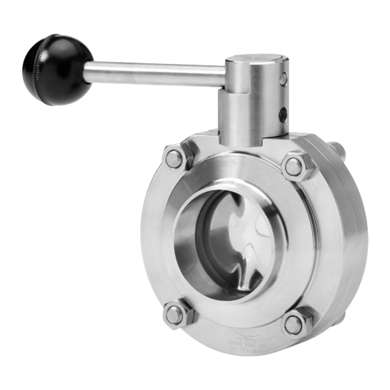
Alfa Laval LKB Instruction Manual

Alfa Laval LKB Instruction Manual

Automatic or manual butterfly valve and low pressure butterfly valve
Hide thumbs Also See for LKB:

Advertisement

Instruction Manual
LKB Automatic or Manual Butterfly Valve and LKB-LP Low Pressure Butterfly Valve
TD 403-284_1
ESE02446-EN19
Original manual
TD 403-262_1
2021-01
TD 403-263
TD 458-002

Advertisement

Table of Contents
loading
Need help?

Need help?

Do you have a question about the LKB and is the answer not in the manual?

Questions and answers

Subscribe to Our Youtube Channel

Summary of Contents for Alfa Laval LKB

  • Page 1 Instruction Manual LKB Automatic or Manual Butterfly Valve and LKB-LP Low Pressure Butterfly Valve TD 403-262_1 TD 403-263 TD 458-002 TD 403-284_1 ESE02446-EN19 2021-01 Original manual...
  • Page 2 CONTACT CSI FOR MORE INFORMATION | CSIDESIGNS.COM | SALES@CSIDESIGNS.COM | 417.831.1411...
  • Page 3: Table Of Contents

    6. Technical data ..................6.1. Technical data ..................7. Parts list and service kits ................7.1. LKB, LKB-2, LKB-F Butterfly valves, drawings ..........7.2. LKB-LP Butterfly valve, drawing ..............7.3. LKLA and LKLA-T actuators Ø85 mm, drawings ..........7.4. LKLA and LKLA-T actuators Ø133 mm, drawings ..........
  • Page 4 Table of contents The information herein is correct at the time of issue but may be subject to change without prior notice 7.20. LKB lockable multiposition handle for valve ............ 7.21. LKB handle 1.1 for butterfly valve ............... 7.22. Handle 1.1 for indication unit ..............
  • Page 5: Ce Declaration Of Incorporation For Machinery

    1 CE Declaration of Incorporation for Machinery Revision of Declaration of Conformity 2013-12-03 The Designated Company Alfa Laval Kolding A/S Company Name Albuen 31, DK-6000 Kolding, Denmark Address +45 79 32 22 00 Phone No. hereby declare that Valve actuator...
  • Page 6: Safety

    2 Safety Unsafe practices and other important information are highlighted in this manual. Warnings are emphasized by means of special signs. 2.1 Important information A A l l w w a a y y s s r r e e a a d d t t h h e e m m a a n n u u a a l l b b e e f f o o r r e e u u s s i i n n g g t t h h e e v v a a l l v v e e ! ! W W A A R R N N I I N N G G Indicates that special procedures m m u u s s t t be followed to avoid serious personal injury.
  • Page 7: Safety Precautions

    A A l l w w a a y y s s fit the end cap with the “mushrooms” turned outwards and position it correctly before supplying compressed air to the actuator. A A l l w w a a y y s s use Alfa Laval genuine spare parts. The warranty of Alfa Laval products is dependent on the use of Alfa Laval genuine spare parts.
  • Page 8: Installation

    The items refer to parts list and service kits sections. The valve is supplied as separate parts as standard (for welding) The valve is assembled before delivery, if it is supplied with fittings (LKB/LKB-2) 3.1 Unpacking/delivery S S t t e e p p 1 1 C C A A U U T T I I O O N N Alfa Laval cannot be held responsible for incorrect unpacking.
  • Page 9: General Installation

    3 Installation Read the instructions carefully. The valve has welding ends as standard but can also be supplied with fittings (not LKB-F). NC = Normally closed. NO = Normally open. A/A = Air/air activated. 3.2 General installation S S t t e e p p 1 1 A A l l w w a a y y s s read the technical data thoroughly.
  • Page 10 3 Installation Read the instructions carefully. The valve has welding ends as standard but can also be supplied with fittings (not LKB-F). NC = Normally closed. NO = Normally open. A/A = Air/air activated. A A i i r r c c o o n n n n e e c c t t i i o o n n o o f f a a c c t t u u a a t t o o r r : : R⅛”...
  • Page 11: Welding

    3. If welding both valve body halves, ensure that they can be moved axially B B 1 1 m m m m , so that the valve parts can be removed. 4. After welding, assemble the valve according to steps 1-5, chapter 5.3 Assembly of valve - LKB/LKB-2/LKB-LP L L K K B B - - F F 1.
  • Page 12: Fitting Actuator/Bracket/Handle On The Valve (Optional Extras)

    1. Ensure that the valve is closed by checking the position of the groove of the disc stem top. 2. Fit the actuator/bracket in accordance with chapter 5.3 Assembly of valve - LKB/LKB-2/LKB-LP, Step 4. C C l l o o s s e e d d TD 403-122...
  • Page 13: Recycling Information

    When in doubt, or in the absence of local regulations, please contact your local Alfa Laval sales company CONTACT CSI FOR MORE INFORMATION | CSIDESIGNS.COM | SALES@CSIDESIGNS.COM | 417.831.1411...
  • Page 14: Operation

    See chapter 6 Technical data C C A A U U T T I I O O N N Alfa Laval cannot be held responsible for incorrect operation. S S t t e e p p 2 2 N N e e v v e e r r touch the valve or the pipelines when processing hot liquids Danger of burns! or when sterilising.
  • Page 15: Troubleshooting

    R R e e p p a a i i r r - External leakage - Worn seal ring Replace the seal ring and the bushes - Internal leakage by closed valve - Worn flange seal ring (LKB-F) (normal wear) - External leakage - High pressure - Change rubber grade...
  • Page 16: Recommended Cleaning

    4 Operation The valve is designed for Cleaning In Place (= CIP). Read the instructions carefully and pay special attention to the warnings! NaOH = Caustic Soda. = Nitric acid. 4.3 Recommended cleaning S S t t e e p p 1 1 C C a a u u s s t t i i c c d d a a n n g g e e r r ! ! A A l l w w a a y y s s handle lye and acid with great care.
  • Page 17: Maintenance

    Maintain the valve and the regulator carefully. Read the instructions carefully and pay special attention to the warnings! Always keep spare seal rings, rubber seals, bushes and actuator bearings in stock. Always use Alfa Laval genuine spare parts. ”Mushrooms” = fastening connections on the end cap.
  • Page 18 Maintain the valve and the regulator carefully. Read the instructions carefully and pay special attention to the warnings! Always keep spare seal rings, rubber seals, bushes and actuator bearings in stock. Always use Alfa Laval genuine spare parts. ”Mushrooms” = fastening connections on the end cap.
  • Page 19: Dismantling Of Valve - Lkb/Lkb-2/Lkb-Lp

    LKB: for ISO tubes. LKB-2: for DIN tubes. 5.2 Dismantling of valve - LKB/LKB-2/LKB-LP S S t t e e p p 1 1 V V a a l l v v e e w w i i t t h h a a c c t t u u a a t t o o r r : : 1.
  • Page 20: Assembly Of Valve - Lkb/Lkb-2/Lkb-Lp

    5 Maintenance Read the instructions carefully. The items refer to the parts list and service kits section. LKB: for ISO tubes. LKB-2: for DIN tubes. Lubricate the seal ring before fitting it. Lubricate the disc stem before fitting the bushes.
  • Page 21 5 Maintenance Read the instructions carefully. The items refer to the parts list and service kits section. LKB: for ISO tubes. LKB-2: for DIN tubes. Lubricate the seal ring before fitting it. Lubricate the disc stem before fitting the bushes.
  • Page 22: Dismantling Of Valve - Lkb-F

    The items refer to the parts list and service kits section. Handle scrap correctly. LKB-F: with flange connection. 5.4 Dismantling of valve - LKB-F S S t t e e p p 1 1 1. Loosen the two upper screws and nuts (6).
  • Page 23: Assembly Of Valve - Lkb-F

    Lubricate the seal rings before fitting them. Lubricate the disc stem before fitting the bushes. 5.5 Assembly of valve - LKB-F S S t t e e p p 1 1 1. Lubricate the pin holes in seal ring (5), (important for Silicone and Viton).
  • Page 24: Dismantling Of Actuator

    5 Maintenance Read the instructions carefully. The items refer to the parts list and service kits section. Handle scrap correctly. NC = Normally closed. NO = Normally open. A/A = Air/air activated. 5.6 Dismantling of actuator S S t t e e p p 1 1 1.
  • Page 25: Assembly Of Actuator

    5 Maintenance Read the instructions carefully. NC = Normally closed. NO = Normally open. A/A = Air/air activated. Lubricate the rubber seals before fitting them. Lubricate the bearings. Clean the piston before assembly. 5.7 Assembly of actuator S S t t e e p p 1 1 Fit rotating cylinder (2) in air cylinder (1).
  • Page 26: Technical Data

    NC = Normally closed. NO = Normally open. A/A = Air/air activated. 6.1 Technical data LKB is a sanitary automatically or manually operated butterfly valve for use in stainless steel pipe systems. LKB is either remote-controlled by means of an actuator or manually operated by means of a handle.
  • Page 27 6 6 5 5 8 8 0 0 1 1 0 0 0 0 1 1 2 2 5 5 1 1 5 5 0 0 Weight LKB-F with welding 11.7 12.3 ends and handle Weight LKB/LKB-2 with welding ends and handle Weight LKB-F with welding 19.5...
  • Page 28: Lkb, Lkb-2, Lkb-F Butterfly Valves, Drawings

    7 Parts list and service kits The drawings include all parts of the valves. For the parts list, please see chapters 7.5 LKB Butterfly valve, ISO, 7.6 LKB-F Butterfly valves, ISO, 7.7 LKB-F Butterfly valves, DIN, 7.8 LKB-2 Butterfly valves Always use Alfa Laval genuine spare parts.
  • Page 29: Lkb-Lp Butterfly Valve, Drawing

    7 Parts list and service kits The drawings include all parts of the actuators. For the parts list, please see chapter 7.9 LKB-LP Butterfly valve 7.2 LKB-LP Butterfly valve, drawing CONTACT CSI FOR MORE INFORMATION | CSIDESIGNS.COM | SALES@CSIDESIGNS.COM | 417.831.1411...
  • Page 30: Lkla And Lkla-T Actuators Ø85 Mm, Drawings

    7 Parts list and service kits The drawings include all parts of the actuators. For the parts list, please see chapters 7.10 LKLA ø85 mm (NO/NC) - 7.19 LKLA-T ø133 mm (A/A). 7.3 LKLA and LKLA-T actuators Ø85 mm, drawings L L K K L L A A - - T T ( ( N N C C - - N N O O ) ) L L K K L L A A - - T T ( ( A A / / A A ) ) TD 403-132...
  • Page 31 7 Parts list and service kits The drawings include all parts of the actuators. For the parts list, please see chapters 7.10 LKLA ø85 mm (NO/NC) - 7.19 LKLA-T ø133 mm (A/A). D D N N 1 1 2 2 5 5 - - 1 1 5 5 0 0 ( ( A A / / A A ) ) 403-138 CONTACT CSI FOR MORE INFORMATION | CSIDESIGNS.COM | SALES@CSIDESIGNS.COM | 417.831.1411...
  • Page 32 CONTACT CSI FOR MORE INFORMATION | CSIDESIGNS.COM | SALES@CSIDESIGNS.COM | 417.831.1411...
  • Page 33: Lkla And Lkla-T Actuators Ø133 Mm, Drawings

    7 Parts list and service kits The drawings include all parts of the actuators. For the parts list, please see chapters 7.10 LKLA ø85 mm (NO/NC) - 7.19 LKLA-T ø133 mm (A/A). 7.4 LKLA and LKLA-T actuators Ø133 mm, drawings L L K K L L A A - - T T ( ( N N C C - - N N O O ) ) L L K K L L A A - - T T ( ( A A / / A A ) ) TD 403-134...
  • Page 34: Lkb Butterfly Valve, Iso

    7 Parts list and service kits The drawing and parts list include all items of the valve. 7.5 LKB Butterfly valve, ISO CONTACT CSI FOR MORE INFORMATION | CSIDESIGNS.COM | SALES@CSIDESIGNS.COM | 417.831.1411...
  • Page 35 7 Parts list and service kits The drawing and parts list include all items of the valve. P P a a r r t t s s l l i i s s t t Pos. Denomination Valve body half Disc Bush ...
  • Page 36: Lkb-F Butterfly Valves, Iso

    7 Parts list and service kits The drawing and parts list include all items of the valve. 7.6 LKB-F Butterfly valves, ISO CONTACT CSI FOR MORE INFORMATION | CSIDESIGNS.COM | SALES@CSIDESIGNS.COM | 417.831.1411...
  • Page 37 7 Parts list and service kits The drawing and parts list include all items of the valve. P P a a r r t t s s l l i i s s t t Pos. Denomination Valve body half Disc Bush ...
  • Page 38: Lkb-F Butterfly Valves, Din

    7 Parts list and service kits The drawing and parts list include all items. 7.7 LKB-F Butterfly valves, DIN CONTACT CSI FOR MORE INFORMATION | CSIDESIGNS.COM | SALES@CSIDESIGNS.COM | 417.831.1411...
  • Page 39 7 Parts list and service kits The drawing and parts list include all items. P P a a r r t t s s l l i i s s t t Pos. Denomination Valve body half Disc Bush  Bush set (10 pcs.) Bush set (10 pcs) Bush set (10 pcs)
  • Page 40: Lkb-2 Butterfly Valves

    7 Parts list and service kits The drawing and parts list include all items. 7.8 LKB-2 Butterfly valves TD 403-231_2 CONTACT CSI FOR MORE INFORMATION | CSIDESIGNS.COM | SALES@CSIDESIGNS.COM | 417.831.1411...
  • Page 41 7 Parts list and service kits The drawing and parts list include all items. P P a a r r t t s s l l i i s s t t Pos. Denomination Valve body half Valve body half Disc Bush ...
  • Page 42: Lkb-Lp Butterfly Valve

    7 Parts list and service kits The drawing and parts list include all items. 7.9 LKB-LP Butterfly valve TD 458-001_1 CONTACT CSI FOR MORE INFORMATION | CSIDESIGNS.COM | SALES@CSIDESIGNS.COM | 417.831.1411...
  • Page 43 7 Parts list and service kits The drawing and parts list include all items. P P a a r r t t s s l l i i s s t t Pos. Denomination Valve body half Disc Bush  Bush, set (10 pcs.) Bush ...
  • Page 44: Lkla Ø85 Mm (No/Nc)

    7 Parts list and service kits The drawing and the parts list include all items. NO = Normally open. NC = Normally closed. 7.10 LKLA ø85 mm (NO/NC) CONTACT CSI FOR MORE INFORMATION | CSIDESIGNS.COM | SALES@CSIDESIGNS.COM | 417.831.1411...
  • Page 45 7 Parts list and service kits The drawing and the parts list include all items. NO = Normally open. NC = Normally closed. P P a a r r t t s s l l i i s s t t S S e e r r v v i i c c e e k k i i t t s s Pos.
  • Page 46: Lkla Ø85 Mm (A/A)

    7 Parts list and service kits The drawing and the parts list include all items. 7.11 LKLA ø85 mm (A/A) TD 407-024_1 CONTACT CSI FOR MORE INFORMATION | CSIDESIGNS.COM | SALES@CSIDESIGNS.COM | 417.831.1411...
  • Page 47 7 Parts list and service kits The drawing and the parts list include all items. P P a a r r t t s s l l i i s s t t S S e e r r v v i i c c e e k k i i t t s s Service kits, air/air .
  • Page 48: Lkla Dn 125-150 Ø85 Mm (A/A)

    7 Parts list and service kits The drawing and the parts list include all items 7.12 LKLA DN 125-150 ø85 mm (A/A) TD 407-023_1 CONTACT CSI FOR MORE INFORMATION | CSIDESIGNS.COM | SALES@CSIDESIGNS.COM | 417.831.1411...
  • Page 49 7 Parts list and service kits The drawing and the parts list include all items P P a a r r t t s s l l i i s s t t S S e e r r v v i i c c e e k k i i t t s s Pos.
  • Page 50: Lkla Ø133 Mm (No/Nc)

    7 Parts list and service kits The drawing and the parts list include all items. NO = Normally open. NC = Normally closed. 7.13 LKLA ø133 mm (NO/NC) TD 407-022_1 CONTACT CSI FOR MORE INFORMATION | CSIDESIGNS.COM | SALES@CSIDESIGNS.COM | 417.831.1411...
  • Page 51 7 Parts list and service kits The drawing and the parts list include all items. NO = Normally open. NC = Normally closed. P P a a r r t t s s l l i i s s t t S S e e r r v v i i c c e e k k i i t t s s Pos.
  • Page 52: Lkla Ø133 Mm (A/A)

    7 Parts list and service kits The drawing and the parts list include all items. 7.14 LKLA ø133 mm (A/A) TD 407-021_1 CONTACT CSI FOR MORE INFORMATION | CSIDESIGNS.COM | SALES@CSIDESIGNS.COM | 417.831.1411...
  • Page 53 7 Parts list and service kits The drawing and the parts list include all items. P P a a r r t t s s l l i i s s t t S S e e r r v v i i c c e e k k i i t t s s Pos.
  • Page 54: Lkla-T Ø85 Mm (No/Nc)

    7 Parts list and service kits The drawing and the parts list include all items. NO = Normally open. NC = Normally closed. 7.15 LKLA-T ø85 mm (NO/NC) TD 407-020_2 CONTACT CSI FOR MORE INFORMATION | CSIDESIGNS.COM | SALES@CSIDESIGNS.COM | 417.831.1411...
  • Page 55 7 Parts list and service kits The drawing and the parts list include all items. NO = Normally open. NC = Normally closed. P P a a r r t t s s l l i i s s t t S S e e r r v v i i c c e e k k i i t t s s Pos.
  • Page 56: Lkla-T Ø85 Mm (A/A)

    7 Parts list and service kits The drawing and the parts list include all items. 7.16 LKLA-T ø85 mm (A/A) CONTACT CSI FOR MORE INFORMATION | CSIDESIGNS.COM | SALES@CSIDESIGNS.COM | 417.831.1411...
  • Page 57 7 Parts list and service kits The drawing and the parts list include all items. P P a a r r t t s s l l i i s s t t S S e e r r v v i i c c e e k k i i t t s s Pos.
  • Page 58: Lkla-T Dn 125-150 Ø85 Mm (A/A)

    7 Parts list and service kits The drawing and the parts list include all items. 7.17 LKLA-T DN 125-150 ø85 mm (A/A) CONTACT CSI FOR MORE INFORMATION | CSIDESIGNS.COM | SALES@CSIDESIGNS.COM | 417.831.1411...
  • Page 59 7 Parts list and service kits The drawing and the parts list include all items. P P a a r r t t s s l l i i s s t t S S e e r r v v i i c c e e k k i i t t s s Service kits, air/air .
  • Page 60: Lkla-T Ø133 Mm (No/Nc)

    7 Parts list and service kits The drawing and the parts list include all items. NO = Normally open. NC = Normally closed. 7.18 LKLA-T ø133 mm (NO/NC) TD 407-017_2 CONTACT CSI FOR MORE INFORMATION | CSIDESIGNS.COM | SALES@CSIDESIGNS.COM | 417.831.1411...
  • Page 61 7 Parts list and service kits The drawing and the parts list include all items. NO = Normally open. NC = Normally closed. P P a a r r t t s s l l i i s s t t S S e e r r v v i i c c e e k k i i t t s s Pos.
  • Page 62: Lkla-T Ø133 Mm (A/A)

    7 Parts list and service kits The drawing and the parts list include all items. 7.19 LKLA-T ø133 mm (A/A) TD 407-016_2 CONTACT CSI FOR MORE INFORMATION | CSIDESIGNS.COM | SALES@CSIDESIGNS.COM | 417.831.1411...
  • Page 63 7 Parts list and service kits The drawing and the parts list include all items. P P a a r r t t s s l l i i s s t t S S e e r r v v i i c c e e k k i i t t s s Pos.
  • Page 64 7 Parts list and service kits The drawing and the parts list include all items. 7.20 LKB lockable multiposition handle for valve CONTACT CSI FOR MORE INFORMATION | CSIDESIGNS.COM | SALES@CSIDESIGNS.COM | 417.831.1411...
  • Page 65 7 Parts list and service kits The drawing and the parts list include all items. P P a a r r t t s s l l i i s s t t Pos. Denomination Insert Positioning cap Screw CONTACT CSI FOR MORE INFORMATION | CSIDESIGNS.COM | SALES@CSIDESIGNS.COM | 417.831.1411...
  • Page 66 The drawing and the parts list include all items. 7.21 LKB handle 1.1 for butterfly valve Handle 1.1 for LKB butterfly valve TD 403-227_1 Handle 1.1 with infinite positions for LKB Butterfly valve TD 403-228_1 CONTACT CSI FOR MORE INFORMATION | CSIDESIGNS.COM | SALES@CSIDESIGNS.COM | 417.831.1411...
  • Page 67 7 Parts list and service kits The drawing and the parts list include all items. P P a a r r t t s s l l i i s s t t Pos. Denomination Transfer block Handle Screw with pin Spring Ball CONTACT CSI FOR MORE INFORMATION | CSIDESIGNS.COM | SALES@CSIDESIGNS.COM | 417.831.1411...
  • Page 68 7 Parts list and service kits The drawing and the parts list include all items. 7.22 Handle 1.1 for indication unit TD 403-226_1 CONTACT CSI FOR MORE INFORMATION | CSIDESIGNS.COM | SALES@CSIDESIGNS.COM | 417.831.1411...
  • Page 69 7 Parts list and service kits The drawing and the parts list include all items. P P a a r r t t s s l l i i s s t t Pos. Denomination Location cap with 2 pos. Transfer block Handle Screw with pin...
  • Page 70 © Alfa Laval Corporate AB This document and its contents is owned by Alfa Laval Corporate AB and protected by laws governing intellectual property and thereto related rights. It is the responsibility of the user of this document to comply with all applicable intellectual property laws. Without limiting any rights related to this document, no part of this document may be copied, reproduced or transmitted in any form or by any means (electronic, mechanical, photocopying, recording, or otherwise), or for any purpose, without the expressed permission of Alfa Laval Corporate AB.

This manual is also suitable for:

Lkb-lpLkb-2Lkb-fLklaLkla-t

Table of Contents