
Related Manuals for CYP CPHD-V4L


Summary of Contents for CYP CPHD-V4L
- Page 1 CPHD-V4L (Dark Case) 4K UHD HDMI Signal Generator & Analyzer (Portable Version) Operation Manual Operation Manual...
- Page 2 ® registered trademarks of HDMI licensing Administrator, Inc.
- Page 3 DISCLAIMERS The information in this manual has been carefully checked and is believed to be accurate. Cypress Technology assumes no responsibility for any infringements of patents or other rights of third parties which may result from its use. Cypress Technology assumes no responsibility for any inaccuracies that may be contained in this document.
- Page 4 SAFETY PRECAUTIONS Please read all instructions before attempting to unpack, install or operate this equipment and before connecting the power supply. Please keep the following in mind as you unpack and install this equipment: • Always follow basic safety precautions to reduce the risk of fire, electrical shock and injury to persons.
-
Page 5: Table Of Contents
CONTENTS 1. Introduction ............1 2. Applications ............1 3. Package Contents ..........1 4. System Requirements .........2 5. Features..............2 6. Operation Controls and Functions ....3 6.1 Front Panel ............3 6.2 Top Panel ............5 6.3 Battery Compartment ........6 6.4 Serial via USB Defaults ........7 6.5 OLED Display ..........8 6.5.1 Power Saving Mode .......8 6.5.2 Special OLED Icons .......8... -
Page 6: Introduction
1. INTRODUCTION This portable HDMI Signal Generator & Analyzer provides a convenient way to test and verify all aspects of an HDMI signal path, including source and sink. This unit complies with the HDMI 2.0a and HDCP 1.4/2.2 standards. The unit’s Analyzer mode complies with the CEA standard HDR static metadata extensions CEA-861-F and CEA-861.3 for EDID analysis. -
Page 7: System Requirements
4. SYSTEM REQUIREMENTS • HDMI receiving equipment such as an HDTV, monitor or audio amplifier and/or HDMI source equipment such as a media player, video game console or set-top box. • For portable operation, a battery (not included) is required. The Panasonic NCR18650B (3.6V/3350mAh) Lithium-ion rechargeable battery, or similar, is recommended. -
Page 8: Operation Controls And Functions
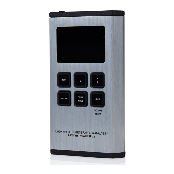
6. OPERATION CONTROLS AND FUNCTIONS 6.1 Front Panel MENU TASK ENTER HDCP MODE FACTORY RESET UHD+ PATTERN GENERATOR & ANALYZER OLED: This screen’s layout changes depending on the unit’s operational mode and selected function. The status lines at the top shows the unit’s current operational mode (Analyzer, Pattern, or Cable Test), USB port mode (power or control), power status, and mode specific detection details. - Page 9 Pattern Mode: The status line will display the RxSense and Hot-plug detection state of the connected display. (1 = detected, 0 = not detected.) Cable Test Mode: The status line will display a cable connection graphic. BATTERY CHARGING LED: The battery charging LED will illuminate red when a USB power source is connected and actively charging the battery.
-
Page 10: Top Panel
HDCP Button: Press to switch between supported HDCP versions (1.4, 2.2) or to disable HDCP. In Analyzer mode, this changes the HDCP versions supported by the input port. In Pattern mode, this changes the HDCP required by the output port. The button’s outline will light up according to the HDCP state and current version supported. -
Page 11: Battery Compartment
6.3 Battery Compartment While this unit may be powered directly via the USB port, it is more typically powered by a rechargeable Lithium-ion battery (not included) which is concealed within the bottom of the unit. Opening the Compartment: Use a small flathead screwdriver to gently, but firmly, press down into the slot behind the base panel and the bottom cover will pop out. -
Page 12: Serial Via Usb Defaults
6.4 Serial via USB Defaults When the unit is set to RS-232 mode in the System menu and connected to a PC via a USB cable, the following COM port settings should be used for direct control. Serial via USB Default Settings Baud Rate 115200 Data Bits... -
Page 13: Oled Display
6.5 OLED Display 6.5.1 Power Saving Mode The OLED display will automatically switch off after the set number of minutes. All other functions of the unit will continue normally while the display is turned off and the HDCP button will slowly flash red to indicate it is in power saving mode. -
Page 14: Oled Menu
6.6 OLED Menu All functions of this unit can be controlled by using the OLED Menu. Use the +/▲, −/▼, and ENTER buttons to navigate the OLED menu. Press the ENTER button to confirm a selection within the menu or to go deeper into a menu item. - Page 15 INPUT SETUP 2ND LEVEL 3RD LEVEL 50ms ~ 500ms (150ms) Hotplug Time Hotplug Toggle RxSense *PoR DDC Bus *PoR HDCP Port v1.4 *PoR V1.4 + V2.2 HDCP REAUTH-REQ 4K to 1080p On YCbCr Out On RGB Out SCDC Port *PoR PC Tolerance 1~10 (1) 1) Hotplug Time: Set the length of time for the hot plug to last (in...
- Page 16 7) 4K to 1080: Select how the unit will handle 4K sources. Selecting “Off” will bypass all sources without modification. Selecting “YCbCr Out” or “RGB Out” will scale 4K sources to 1080p and use the selected color space for the output signal. Note: When scaling is enabled, no frame rate conversion is performed.
- Page 17 - SPD: Source Product Description infoframe packet. - 3D: 3D video content. MONITOR HDCP (Active HDCP 1.4 Source) 2ND LEVEL 3RD LEVEL Source HDCP Rx HDCP Port Aksv Bksv [Current Analytical Data] Ri Source Ri’ Rx Count Day 0 00:00:00 1) Monitor HDCP (Active HDCP 1.4 Source): This page displays the real-time details of HDCP 1.4 communication between this unit and the source currently connected to the HDMI input.
- Page 18 1) Monitor HDCP (Active HDCP 2.2 Source): This page displays the real-time details of HDCP 2.2 communication between this unit and the source currently connected to the HDMI input. Note: These details will only display when the source is encrypted with HDCP 2.2.
- Page 19 VIDEO TIMING 2ND LEVEL 3RD LEVEL TMDS [Current Analytical Data] (8/10/12)B, 3D, Y420, Scr [Highlighted when detected] Total Polarity Scan [Current Analytical Data] HFreq VFreq Offset1 Offset2 1) Video Timing: This page displays the real-time details of the video source currently detected on the HDMI input. Note: Because 4K YUV 4:2:2 video does not report a bit depth and always uses 12-bits of space for color, even with 8-bit content, it will always be reported as 12-bit.
- Page 20 - VFreq: Vertical sync frequency. - Offset1: Vertical line offset of an interlaced source’s odd field. - Offset2: Vertical line offset of an interlaced source’s even field. Note: When the source is progressive scan, Offset 2 will display “Invalid”. AUDIO TIMING 2ND LEVEL 3RD LEVEL ACR, AIF, ASP, HBR...
- Page 21 - C.Coding: Channel audio encoding. - C.Ch No.: Number of audio channels. - C.Src No.: Number of channel sources. - C.Sample Rate: Channel sampling rate. - C.Sample Size: Channel sampling size. PACKET 2ND LEVEL 3RD LEVEL GCP 0x03 AVI 0x82 AIF 0x84 [Current Analytical Data] SPD 0x83...
- Page 22 EDID ANALYZER 2ND LEVEL 3RD LEVEL Sink [Current Analytical Data] Rx EDID [D1] DVI [D2] VGA [D3] 8B LPCM PC [D4] 8B LPCM HD [D5] 12 BS 720p [Default EDID Details] [D6] 12 BS HD 3D [D7] 12 BS 4K6G [D8] 12 HBR 4K3G [D9] 12 HBR 4K420 [D10] 12 HBR 4K6G...
- Page 23 EDID EMULATOR 2ND LEVEL 3RD LEVEL Copy Sink [Use Sink EDID] [D1] DVI [D2] VGA [D3] 8B LPCM PC [D4] 8B LPCM HD [D5] 12 BS 720p [Use Selected EDID] [D6] 12 BS HD 3D [D7] 12 BS 4K6G [D8] 12 HBR 4K3G [D9] 12 HBR 4K420 [D10] 12 HBR 4K6G [C1~10] Copy 01~10...
- Page 24 EDID BURN SINK 2ND LEVEL 3RD LEVEL [D1] DVI [D2] VGA [D3] 8B LPCM PC [D4] 8B LPCM HD [D5] 12 BS 720p [Overwrite Sink’s EDID [D6] 12 BS HD 3D with the Selected EDID] [D7] 12 BS 4K6G [D8] 12 HBR 4K3G [D9] 12 HBR 4K420 [D10] 12 HBR 4K6G [C1~10] Copy 01~10...
- Page 25 SETUP 2ND LEVEL 3RD LEVEL POWER USB Port RS-232 0~8 (8) OLED Contrast Firmware Upd Power Saving 2~10min (10) EDID Reset Factory Rst 1) USB Port: Select the USB port’s operational mode. 2) OLED Contrast: Set the OLED screen’s contrast level. 3) Firmware Update: Provides a way to update the unit’s firmware.
-
Page 26: Pattern Mode
6.6.2 Pattern Mode MAIN MENU Output Setup Monitor Sink Monitor HDCP Monitor SCDC Audio Output EDID Analyzer EDID Emulator EDID Copy Sink EDID Burn Sink HDR Emulator Setup Information OUTPUT SETUP 2ND LEVEL 3RD LEVEL Timing [T1] 720x480p59 [T2] 720x576p50 [T3] 1280x720p25 [T4] 1280x720p30 [T5] 1280x720p50... - Page 27 OUTPUT SETUP 2ND LEVEL 3RD LEVEL [T14] 3840×2160p24 [T15] 3840×2160p25 [T16] 3840×2160p30 [T17] 3840×2160p50 [T18] 3840×2160p60 [T19] 4096×2160p24 [T20] 4096×2160p25 [T21] 4096×2160p30 [T22] 4096×2160p50 [T23] 4096×2160p60 Pattern [P1] Black [P2] Blue [P3] Cyan [P4] Green [P5] Magenta [P6] Red [P7] White [P8] Yellow [P9] COLOR BAR [P10] Grayscale 256...
- Page 28 OUTPUT SETUP 2ND LEVEL 3RD LEVEL HDMI Format Colorspace Y444 Y422 Y420 ColorRange FULL Limited Audio LPCM *PoR 5.1Ch 7.1CH HDCP Out v1.4 v2.2 HDCP Store K HDCP2 Rep.Type *PoR GCP AVMute *PoR Output *PoR FOLLOW +5V Out...
- Page 29 1) Timing: Select the output resolution and refresh rate. 2) Pattern: Select the test pattern to display. 3) Format: Select the video format for the output. Note: DVI mode does not support audio output or the YUV color space. 4) Colorspace: Select the color space format for the video output. Note: Available color space formats will vary depending on the standards supported by the selected output resolution.
- Page 30 MONITOR SINK 2ND LEVEL 3RD LEVEL HDCP Port/Auth EDID [Current Analytical Data] SCDC Port 1) Monitor Sink: This page displays a basic analysis of the current HDCP, EDID and SCDC capability information reported by the connected display. MONITOR HDCP (HDCP 1.4 Output) 2ND LEVEL 3RD LEVEL Tx HDCP...
- Page 31 MONITOR HDCP (HDCP 2.2 Output) 2ND LEVEL 3RD LEVEL Tx HDCP Sink HDCP Port TxCaps RxCaps Receiver ID Rep.Auth [Current Analytical Data] Rep.Depth Rep.Device Rep.C.Type Stored km Sink REAUTH Count Day 0 00:00:00 1) Monitor HDCP (HDCP 2.2 Output): This page displays the real- time details of HDCP 2.2 communication between this unit and the device currently connected to the HDMI output.
- Page 32 MONITOR SCDC 2ND LEVEL 3RD LEVEL Sink SCDC Pt Sink Version Source Ver Scramble Ena Scramble Sta [Current Analytical Data] Clock Detect Ch2/1/0 Locked CED Ch0 CED Ch1 CED Ch2 ENTER Reset/Start [Sink EDID] HF VSDB [Current Analytical Data] [Sink EDID] SCDC Exist 1) Monitor SCDC: This page displays the details of the SCDC (Status and Control Data Channel) of the display currently connected to the HDMI output.
- Page 33 AUDIO OUTPUT 2ND LEVEL 3RD LEVEL 0~80 (70) Volume Sample Rate 48 KHZ 96 KHz 192 KHz Word Length 16 Bits 20 Bits 24 BITS Channels *PoR SD0-L ~ SD3-L Freq. 200Hz ~ 1600Hz (1000Hz) Mute SD0-R ~ SD3-R Freq. 200Hz ~ 1600Hz (1000Hz) Mute 1) Volume: Set the global test tone output volume.
- Page 34 EDID ANALYZER 2ND LEVEL 3RD LEVEL Sink [Current Analytical Data] Rx EDID [D1] DVI [D2] VGA [D3] 8B LPCM PC [D4] 8B LPCM HD [D5] 12 BS 720p [Default EDID Details] [D6] 12 BS HD 3D [D7] 12 BS 4K6G [D8] 12 HBR 4K3G [D9] 12 HBR 4K420 [D10] 12 HBR 4K6G...
- Page 35 EDID EMULATOR 2ND LEVEL 3RD LEVEL Copy Sink [Use Sink EDID] [D1] DVI [D2] VGA [D3] 8B LPCM PC [D4] 8B LPCM HD [D5] 12 BS 720p [Use Selected EDID] [D6] 12 BS HD 3D [D7] 12 BS 4K6G [D8] 12 HBR 4K3G [D9] 12 HBR 4K420 [D10] 12 HBR 4K6G [C1~10] Copy 01~10...
- Page 36 EDID BURN SINK 2ND LEVEL 3RD LEVEL [D1] DVI [D2] VGA [D3] 8B LPCM PC [D4] 8B LPCM HD [D5] 12 BS 720p [Overwrite Sink’s EDID [D6] 12 BS HD 3D with the Selected EDID] [D7] 12 BS 4K6G [D8] 12 HBR 4K3G [D9] 12 HBR 4K420 [D10] 12 HBR 4K6G [C1~10] Copy 01~10...
- Page 37 HDR EMULATOR 2ND LEVEL 3RD LEVEL EOTF [0] SDR Lumi Range [1] HDR Lumi Range [2] SMPTE ST2084.2 [3] Future EOTF Metadata Descr. S. METADATA TYPE 1 Reserved Max. Content L-L 0~65500 (0) 0~65500 (0) Max. FrameAve LL AVI Color Space [Current Analytical Data] Sink EDID HDR 1) HDR Out: Enable or disable the HDR output simulation mode.
- Page 38 SETUP 2ND LEVEL 3RD LEVEL POWER USB Port RS-232 0~8 (8) OLED Contrast Firmware Upd Power Saving 2~10min (10) EDID Reset Factory Rst 1) USB Port: Select the USB port’s operational mode. 2) OLED Contrast: Set the OLED screen’s contrast level. 3) Firmware Update: Provides a way to update the unit’s firmware.
-
Page 39: Cable Test Mode
6.6.3 Cable Test Mode MAIN MENU Run Test Cable Setup Setup Information RUN TEST 2ND LEVEL 3RD LEVEL [Testing Configuration] Hotplug [Analytic Data] DDC Bus (PASS or FAIL Result) ARC* 4K6G A/V 1) Run Test: This menu allows the activation of the cable test and displays the results of the test across 2 pages. - Page 40 CABLE SETUP 2ND LEVEL 3RD LEVEL Type COPPER Optical Delay NORMAL Level Strict Length 2 MINUTE Time 5 minute 10 minute 15 minute 30 minute 1 hour Infinite 1) Type: Select the type of cable being tested, standard copper cable or optical (AOC) cable.
- Page 41 SETUP 2ND LEVEL 3RD LEVEL POWER USB Port RS-232 0~8 (8) OLED Contrast Firmware Upd Power Saving 2~10min (10) EDID Reset Factory Rst 1) USB Port: Select the USB port’s operational mode. 2) OLED Contrast: Set the OLED screen’s contrast level. 3) Firmware Update: Provides a way to update the unit’s firmware.
-
Page 42: Test Timings & Patterns
6.7 Test Timings & Patterns 6.7.1 Resolution Support (Analyzer Mode) This unit provides 3 options for how to handle the output of 4K video input sources when in Analyzer Mode. These choices are selectable from the “Input Setup” menu using the “4K to 1080p” item. 1) To scale 4K sources down to 1080p and output using the YCbCr color space, select “On YCbCr Out”. -
Page 43: Test Patterns (Pattern Mode)
6.7.3 Test Patterns (Pattern Mode) There are a total of 17 test patterns available for output when in Pattern Mode. Test Pattern Name Test Pattern Name P01 Grayscale 256 Black Blue P02 Line On/Off-V P03 Circle Cyan Green P04 Crosshatch P05 Crosshatch I Magenta P06 Diagonal... - Page 44 P09 - Color Bar The Color Bar pattern is a series of repeating vertical colored bars (white, yellow, cyan, green, magenta, red, blue, black). Note: Selecting this pattern will force the output color range to change to “Full”. P10 - Grayscale 256 The Grayscale 256 pattern provides a way to fine tune the contrast, brightness and grayscale tracking of your display with a full 265 step gradient progressing...
- Page 45 P12 - Circle The Circle pattern provides 1 large white circle in the center and 2 smaller white circles in the upper left and lower right corners of the screen. All 3 circles have center crosses. This pattern can help confirm that the display is maintaining correct geometry across the entire screen.
-
Page 46: Audio Output Support (Pattern Mode)
P15 - Diagonal The Diagonal pattern is two crossing sets of 3 diagonal lines that travel through the exact center of the display. The outer border of the pattern also has a white outline. This pattern can be used to check for alignment and geometry issues, or to help align multi- display video walls. -
Page 47: Serial Commands
6.8 Serial Commands Before using these commands, please read the following: Syntax: All commands MUST start with the “$” character or the command will not be recognized by the unit. Commands must end with a carriage return (0x0D). Use of a line feed (0x0A) is optional. Commands are not case- sensitive. - Page 48 COMMAND Description and Parameters $AUDIO_CH N1 Set the number of internally sourced audio output channels. Available values for N1: [2 Channels (2.0)] [6 Channels (5.1)] [8 Channels (7.1)] $AUDIO_CH? Show the current number of audio output channels. $AUDIO_FREQ N1,N2 Set the internal audio output frequency of the selected channel (in Hz). Available Values for N1: SD0_L [SD0 Left Channel]...
- Page 49 COMMAND Description and Parameters $AUDIO_FREQ? N1 Show the internal audio output frequency of the selected channel (in Hz). Available Values for N1: SD0_L [SD0 Left Channel] SD0_R [SD0 Right Channel] SD1_L [SD1 Left Channel] SD1_R [SD1 Right Channel] SD2_L [SD2 Left Channel] SD2_R [SD2 Right Channel] SD3_L...
- Page 50 COMMAND Description and Parameters $BOARD_ID? Show the current board ID. $BOOT GO Reboot the unit. Note: The unit won’t respond to any commands during the boot process. $BOOT? Show the current boot state. $CABLE_DELAY N1 Turn the cable delay on or off. Available values for N1: [Cable delay enabled] [Cable delay disabled]...
- Page 51 COMMAND Description and Parameters $CABLE_LEVEL? Show the cable test level. $CABLE_RESULT? Show the cable test result. $CABLE_RESULT_I? Show the cable test item result. $CABLE_RUN N1 Start or stop the cable testing process. Available values for N1: START [Start testing] STOP [Stop testing] $CABLE_RUN?...
- Page 52 COMMAND Description and Parameters $CABLE_TYPE? Show the cable type. $COLOR_SPACE N1 Set the output color space. Available values for N1: [RGB color space] Y444 [YCbCr (4:4:4) color space] Y422 [YCbCr (4:2:2) color space] Y420 [YCbCr (4:2:0) color space] $COLOR_SPACE? Show the current output color space. $EDID_COPY_SINK N1...
- Page 53 COMMAND Description and Parameters $EDID_NAME N1,N2 Set the EDID name of the selected copy slot. N1 = C1~C10 [User EDID copy slot index] N2 = {Name} [20 characters max] $EDID_NAME? N1 Show the name of the selected EDID slot. Available values for N1: D1~D10 [Default EDID slot index] C1~C10...
- Page 54 COMMAND Description and Parameters $EDID_READ N1,N2 Show the selected data block stored in the EDID of the selected location. This data is output as a bit stream of 128 bytes following the <CR><LF> of the command acknowledgement. Each hex data unit is composed of 3 digits.
- Page 55 COMMAND Description and Parameters $EDID_WRITE N1,N2 N3 Directly write an EDID block to the selected EDID location. The data must be sent as a 128 byte hex data bit stream following the <CR><LF> in the N3 part of the command. Each hex data unit is composed of 3 digits.
- Page 56 COMMAND Description and Parameters $HDCP_IN_VER N1 Set the HDCP version to use on the unit’s HDMI input. Available values for N1: V1.4 [HDCP v1.4 only] V1.4+V2.2 [HDCP v1.4 & v2.2] Note: Analyzer mode only. $HDCP_IN_VER? Show the current HDCP version used on the unit’s HDMI input. $HDCP_OUT_SW N1...
- Page 57 COMMAND Description and Parameters $HDR_EOTF N1 Set the HDR EOTF (Electro-Optical Transfer Function) mode. Available values for N1: [Traditional gamma, SDR luminance range] [Traditional gamma, HDR luminance range] 2084 [SMPTE ST 2084] RSVD [Reserved for future use] $HDR_EOTF? Show the current HDR EOTF mode. $HDR_MCLL N1...
- Page 58 COMMAND Description and Parameters $HDR_TX_COL N1 Set the HDMI output (Tx) AVI colorimetry mode. Available values for N1: [No Data] [ITU 601] [ITU 709] [xvYCC 601] [xvYCC 709] [sYCC 601] [Adobe Y601] [Adobe RGB] [BT.2020 (1) Y’ C’ C’ [BT.2020 (2) R’G’B’/Y’C’ C’...
- Page 59 COMMAND Description and Parameters $RX_DDC N1 Enable or disable the DDC bus for the HDMI input (Rx). Available values for N1: [DDC bus enabled] [DDC bus disabled] $RX_DDC? Show the DDC bus state for the HDMI input (Rx). $RX_HOTPLUG N1 Set the hot plug value for the HDMI input (Rx).
- Page 60 COMMAND Description and Parameters $RX_SCDC N1 Enable or disable the SCDC port function on the HDMI input (Rx). Available values for N1: [SCDC port enabled] [SCDC port disabled] $RX_SCDC? Show the current SCDC port state for the HDMI input (Rx). $RX_SENSE N1...
- Page 61 COMMAND Description and Parameters $SOURCE_DETECT? N1 Show a variety of source detection status and informational values. Available values for N1: [5V detection state] HDCP [Source HDCP status detection] HDCP_AKSV [Source AKSV in hex (HDCP v1.4)] HDCP_BKSV [Rx BKSV in hex (HDCP v1.4)] HDCP_RXID [HDCP Receiver ID in hex (HDCP v2.2)] SCDC_SCR_ENABLE [Rx SCDC source enable scrambling state]...
- Page 62 COMMAND Description and Parameters ASP_LAYOUT [Audio-Sample packet layout] ASP_PLL [Audio-Sample packet PLL] CHS_CODE [Channel-status audio coding] CHS_SR [Channel-status sampling rate in kHz] CHS_SS [Channel-status sampling size] CHS_TYPE [Channel-status app type] [High-Bit-Rate packet status] [Display packet-AIF data in 2-digit hex] [Display packet-AVI data] DRMI [Display packet-DRMI data] [Display packet-GCP data]...
- Page 63 COMMAND Description and Parameters $TIMING N1 Select the output resolution timing to use. Available values for N1: [720×480p@59] [720×576p@50] [1280×720p@25] [1280×720p@30] [1280×720p@50] [1280×720p@60] [1920×1080i@50] [1920×1080i@60] [1920×1080p@24] [1920×1080p@25] [1920×1080p@30] [1920×1080p@50] [1920×1080p@60] [3840×2160p@24] [3840×2160p@25] [3840×2160p@30] [3840×2160p@50] [3840×2160p@60] [4096×2160p@24] [4096×2160p@25] [4096×2160p@30] [4096×2160p@50] [4096×2160p@60] $TIMING?...
- Page 64 COMMAND Description and Parameters $TMDS_FORMAT? Show the current video output format. $TMDS_SW N1 Enable or disable video output. Available values for N1: [Enable video output] [Disables video output] $TMDS_SW? Show the current video output status. $TX_5V N1 Set the unit’s output +5V pin state to follow the TMDS output state or to always be on.
-
Page 65: Connection Diagram
7. CONNECTION DIAGRAM UHDTV HDMI Source Device HDMI HDMI Output Input PC/Laptop MENU TASK ENTER HDCP MODE FACTORY RESET UHD+ PATTERN GENERATOR & ANALYZER... -
Page 66: Specifications
8. SPECIFICATIONS 8.1 Technical Specifications HDMI Bandwidth 18Gbps Input Port 1×HDMI (Type-A) Output Port 1×HDMI (Type-A) Service/Control Port 1×USB 2.0 (Micro-B) Baud Rate 115200 Power Supply 5V/2.1A USB power Lithium-ion battery (Not included) ESD Protection (HBM) ±8kV (Air Discharge) ±4kV (Contact Discharge) Dimensions (W×H×D) 80mm×124mm×26.5mm [Case Only] 80mm×126mm×26.5mm [All Inclusive]... -
Page 67: Video Specifications
8.2 Video Specifications Output Output Input (Bypass) (Pattern) Supported Resolutions (Hz) HDMI HDMI HDMI 720×400p@70/85 640×480p@60/72/75/85 720×480i@60 720×480p@60 59.94 720×576i@50 720×576p@50 800×600p@56/60/72/75/85 ... - Page 68 Output Output Input (Bypass) (Pattern) Supported Resolutions (Hz) HDMI HDMI HDMI 2560×1440p@60RB 2560×1600p@60RB 2048×1080p@24/25/30 2048×1080p@50/60 3840×2160p@24/25/30 3840×2160p@50/60 (4:2:0) 3840×2160p@24, HDR10 ...
-
Page 69: Audio Specifications
8.3 Audio Specifications 8.3.1 Digital Audio HDMI Input / Output (Bypass) LPCM Max Channels 8 Channels Sampling Rate (kHz) 32, 44.1, 48, 88.2, 96, 176.4, 192 Bitstream Supported Formats Standard & High-Definition HDMI Output (Test Tone Generation) LPCM Max Channels 8 Channels Sampling Rate (kHz) 48, 96, 192... -
Page 70: Cable Specifications
8.4 Cable Specifications 1080p 4K30 4K60 (4:4:4) (4:4:4) Cable Length 8-bit 12-bit 8-bit 8-bit High Speed HDMI Cable HDMI Input HDMI Output Bandwidth Category Examples: • 1080p (FHD Video) - Up to 1080p@60Hz, 12-bit color - Data rates lower than 5.3Gbps or below 225MHz TMDS clock •... -
Page 71: Operational Notes
8.5 Operational Notes • Battery - When the USB port is set to RS-232 mode some power is also provided to the unit via USB, however a properly charged battery is still required to operate the unit. - Many USB hubs do not provide proper 5V power to connected devices. When using a USB hub to connect the unit to a PC, it is strongly recommended to power the unit with a fully charged battery. -
Page 72: Acronyms
9. ACRONYMS ACRONYM COMPLETE TERM Active Optical Cable Audio Return Channel ASCII American Standard Code for Information Interchange Consumer Electronics Control Command-Line Interface Communication Decibel Digital Visual Interface EDID Extended Display Identification Data EOTF Electro-Optical Transfer Function Gbps Gigabits per second Graphical User Interface HDCP High-bandwidth Digital Content Protection... - Page 73 ACRONYM COMPLETE TERM Power-On Reset SCDC Status and Control Data Channel Standard Dynamic Range SMPTE Society of Motion Picture and Television Engineers Signal-to-Noise Ratio THD+N Total Harmonic Distortion plus Noise TMDS Transition-Minimized Differential Signaling 4K UHD 4K Ultra-High-Definition (10.2Gbps max) 4K UHD 4K Ultra-High-Definition (18Gbps max) Universal Serial Bus...
- Page 76 CYPRESS TECHNOLOGY CO., LTD. www.cypress.com.tw...
Need help?
Do you have a question about the CPHD-V4L and is the answer not in the manual?
Questions and answers