
Related Manuals for CYP CPHD-V4


Summary of Contents for CYP CPHD-V4
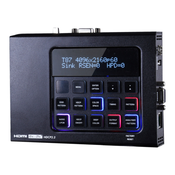
- Page 1 CPHD-V4 4K UHD HDMI Signal Generator & Analyzer (Bench Version) Operation Manual Operation Manual...
- Page 2 ® registered trademarks of HDMI licensing Administrator, Inc.
- Page 3 DISCLAIMERS The information in this manual has been carefully checked and is believed to be accurate. Cypress Technology assumes no responsibility for any infringements of patents or other rights of third parties which may result from its use. Cypress Technology assumes no responsibility for any inaccuracies that may be contained in this document.
- Page 4 SAFETY PRECAUTIONS Please read all instructions before attempting to unpack, install or operate this equipment and before connecting the power supply. Please keep the following in mind as you unpack and install this equipment: • Always follow basic safety precautions to reduce the risk of fire, electrical shock and injury to persons.
-
Page 5: Table Of Contents
CONTENTS 1. Introduction ............1 2. Applications ............. 1 3. Package Contents ........... 1 4. System Requirements ........2 5. Features............2 6. Operation Controls And Functions ....3 6.1 Front Panel ..........3 6.2 Top and Bottom Panels ....... 6 6.3 Left and Right Panels ........ -
Page 6: Introduction
1. INTRODUCTION This HDMI Signal Generator & Analyzer is an advanced and handy tool for generating, testing and verifying the signal path within your 18Gbps HDMI ecosystem. With 90 built-in resolutions, 59 test patterns and dozens of A/V analysis functions, this unit provides an enormous range of testing options. HDMI data packet, EDID and HDCP analysis is supported along with EDID upload and emulation. -
Page 7: System Requirements
4. SYSTEM REQUIREMENTS • HDMI/VGA receiving equipment such as an HDTV, monitor or audio amplifier and/or HDMI source equipment such as a media player, video game console or set-top box. • Analog audio source equipment such as a PC or media player and/or analog audio receiving equipment such as headphones, an audio amplifier or powered speakers. -
Page 8: Operation Controls And Functions
6. OPERATION CONTROLS AND FUNCTIONS 6.1 Front Panel ENTER MENU OPTION EDID HDCP COLOR TIMING PATTERN PATTERN PATTERN SPACE AUDIO DEEP OUTPUT ANALYSER HDCP LPCM ON/OFF COLOR FORMAT / PATTERN FACTORY RESET OLED Display: Displays the current signal analysis information or test pattern mode selection details including input and/or output resolution timing. - Page 9 Once an active sink has been connected, the lower portion of the display will change to indicate the current test pattern number and name. IR Window: Accepts IR signals from the included IR remote for control of this unit only. MENU Button: Press to enter the OSD menu, or to back out from menu items.
- Page 10 Force Hot-Plug: When in Analyzer Mode, press and hold the button for 2 seconds to force a hot-plug on the HDMI input. AV Mute: When in Pattern Mode, press and hold the button for 2 seconds to turn on/off the AVMute bit within the output’s GCP (General Control Packet).
-
Page 11: Top And Bottom Panels
current bit depth: Off=8-bit, Red=10-bit, Blue=12-bit. Note: This control is not valid when the output resolution is set to bypass mode. OUTPUT FORMAT Button: Press to switch between DVI (LED=Blue) and HDMI (LED=Red) output formats. Disable Output: Press and hold the button for 2 seconds to disable/ enable video output completely. -
Page 12: Left And Right Panels
6.3 Left and Right Panels Left POWER Right CONTROL RS232 SERVICE DC 5V POWER Switch: Flip this switch to turn the unit ON or OFF after connecting an appropriate power source. CONTROL Port: Connect directly, or through a network switch, to your PC/laptop to control the unit via Telnet. -
Page 13: Remote Control
6.4 Remote Control Analyser/ HDCP SW. Pattern The IR remote uses one out of 4 available EDID Color Space Format address channels for control of the test pattern WXGA WUXGA generator, allowing up to 4 to be located in the 480p 720p 1080p... -
Page 14: Pinout And Defaults
OK: After selecting a pattern, press and hold for 2 seconds to switch to alternate variations of the pattern. Within the OSD menu, press to confirm selections. Menu: Press to enter the OSD menu. Exit: Press to exit the OSD or cancel the selection. For use in Analyzer Mode only: Source: Press to display source signal information on the OSD. -
Page 15: Osd Menu
6.6 OSD Menu All functions of this unit can be controlled by using the OSD (On Screen Display) which is activated by pressing the MENU button on the front of the unit. Use the + (PLUS), − (MINUS), and ENTER buttons to navigate the OSD menu. -
Page 16: Analyzer Mode
6.6.1 Analyzer Mode SOURCE MONITOR 2ND LEVEL [Resolution Data] [Signal Data] [Packet Data] [Format Data] 1) Source Monitor: This screen displays a simplified collection of data about the current HDMI source. „ Resolution Data: Displays the currently detected resolution and timing information. - Page 17 VIDEO TIMING 2ND LEVEL 3RD LEVEL V Back Porch V Sync Width V Front Porch V Sync Polarity HV Sync Offset 1 HV Sync Offset 2 Scan Mode 1) Video Timing: These pages display the real-time details of the video source currently connected to the HDMI input.
- Page 18 „ HV Sync Offset 2: Vertical line offset of an interlaced source’s even field. „ Scan Mode: Current scan mode (progressive/interlaced). AUDIO TIMING 2ND LEVEL 3RD LEVEL [Current Analytical Data] ACR N ACR CTS -ASP Monitor- FIFO ACR Re-gen [Current Analytical Data] Packet Layout Channel Number Sample Present...
- Page 19 AUDIO TIMING 2ND LEVEL 3RD LEVEL -ASP LPCM Level- SD0-L SD0-R SD1-L SD1-R [Current Analytical Data] SD2-L SD2-R SD3-L SD3-R 1) Audio Timing: These pages display the real-time details of the audio signal currently detected on the HDMI input. Note: Only LPCM sources can be monitored in detail. Bitstream sources will be identified as NLPCM (Not LPCM) and will have reduced information available.
- Page 20 „ SD0 Out Swap: Indicates which Serial Data audio channel pair is currently being output over the primary stereo channel (SD0) for monitoring. This channel can be changed by pressing the “Audio LPCM” button. Note: Not valid when the output resolution is set to “Bypass” mode. „...
- Page 21 PACKET (Monitor) 2ND LEVEL 3RD LEVEL 4TH LEVEL Monitor 1h ACR 2h ASP 3h GCP 4h ACP 5h ISRC1 6h ISRC2 7h One Bit 8h DST 9h HBR Ah Gamut Bh ASP 3D [Current Analytical Data] Ch One Bit 3D Dh Audio Metadata Eh ASP Multi Fh One Bit Multi...
- Page 22 PACKET (GCP) 2ND LEVEL 3RD LEVEL 4TH LEVEL HB0~HB2 SB0~SB4 [Current Analytical Data] SB5~SB6 AVMUTE Color Depth 1) GCP Packet: This page displays the current details contained within the General Control infoframe Packet. PACKET (AVI) 2ND LEVEL 3RD LEVEL 4TH LEVEL Type Version Length...
- Page 23 PACKET (AVI) 2ND LEVEL 3RD LEVEL 4TH LEVEL Non-Uniform Scale VIC 97 YCC Quant.Range IT Contents Type Pixel Repetition 1) AVI Packet: This page displays the current details contained within the Auxiliary Video Information infoframe packet. PACKET (AIF) 2ND LEVEL 3RD LEVEL 4TH LEVEL Type...
- Page 24 PACKET (SPD) 2ND LEVEL 3RD LEVEL 4TH LEVEL Type Version Length Checksum DB 1~DB 5 [Current Analytical DB 6~DB10 Data] DB11~DB15 DB16~DB20 DB21~DB25 Vendor Product Source Information 1) SPD Packet: This page displays the current details contained within the Source Product Description infoframe packet. PACKET (VSIF H14b) 2ND LEVEL 3RD LEVEL...
- Page 25 PACKET (VSIF H14b) 2ND LEVEL 3RD LEVEL 4TH LEVEL IEEE ID HDMI Video Format Ext. HDMI VIC 3D Structure 3D Ext. Data 1) VSIF (HDMI 1.4b) Packet: This page displays the current details contained within the Vendor Specific InfoFrame packet. Note: This information is typically from HDMI 1.4b sources only.
- Page 26 PACKET (DRMI (HDR)) 2ND LEVEL 3RD LEVEL 4TH LEVEL display primaries y2 white point x white point y max disp mastering lumi min disp mastering lum Max Content Light-Level Max Frame-average L-L AVI Color Space AVI Colorimetry 1) DRMI (HDR) Packet: This page displays the current details contained within the Dynamic Range and Mastering Infoframe packet.
- Page 27 EDID ANALYZER 2ND LEVEL 3RD LEVEL 4TH LEVEL HDMI Sink Summary [EDID Data Summary] Block0 Binary List [EDID Block 0 Hex Contents] Vendor/Product ID Display Parameter & Feature Color Characteristic [EDID Block 0 Deciphered Data Established Timings Standard Timings Detail Timings & Monitor Block1 Binary List [EDID Block 1 Hex Contents]...
- Page 28 EDID ANALYZER 2ND LEVEL 3RD LEVEL 4TH LEVEL Default & Copied [D1] DVI EDID [D2] VGA [D3] 8B 2D 2CH LPCM PC [D4] 8B 2D 2CH LPCM HD [D5] 12B 2D 8CH BitS 720p [Same as HDMI [D6] 12B 3D 8CH BitS HD Sink] [D7] 12B 2D 8CH BitS 4K6G [D8] 12B 2D 8CH HBR 4K3G...
- Page 29 EDID EMULATOR 2ND LEVEL 3RD LEVEL Rx EDID Select Copy HDMI Sink [D1] DVI [D2] VGA [D3] 8B 2D 2CH LPCM PC [D4] 8B 2D 2CH LPCM HD [D5] 12B 2D 8CH BitS 720p [D6] 12B 3D 8CH BitS HD [D7] 12B 2D 8CH BitS 4K6G [D8] 12B 2D 8CH HBR 4K3G [D9] 12B 2D 8CH HBR 4K420...
- Page 30 3) Copy VGA Sink EDID to...: Select a Copy EDID numbered slot (C1~C10) to copy and store the EDID from the currently connected VGA display into that slot. The EDID name will be automatically filled in with name data from the copied EDID. Note: If a slot already contains EDID data, it will be overwritten by the new EDID 4) Copy USB Stick EDID to...: Select a Copy EDID numbered slot...
- Page 31 HDCP INPUT MONITOR (HDCP 1.x) 2ND LEVEL 3RD LEVEL Source HDCP Rx HDCP Port Source writes Ainfo to Rx [Current Analytical Data] Source writes An to Rx Source writes Aksv to Rx Source reads Rx Bksv -Link Integrity- Ri Source Ri’...
- Page 32 HDCP INPUT MONITOR (HDCP 2.2) 2ND LEVEL 3RD LEVEL Source HDCP Rx HDCP Port TxCaps Receiver ID [Current Analytical Data] RxCaps Ekpub_km Ekh_km Edkey_ks 1) HDCP Input Monitor (HDCP 2.2): This page displays the real-time details of HDCP 2.2 communication between this unit and the source currently connected to the HDMI input.
- Page 33 SCDC INPUT MONITOR 2ND LEVEL 3RD LEVEL Rx SCDC Port Sink Version Source Version Scrambling Enable TMDS Bit Clock Ratio Scrambling Status RR Enable Test Read Request Test Read Delay RR Test [Current Analytical Data] Status Update Clock Detected Ch2/1/0 Locked CED Update Count CED Count Ch0...
- Page 34 SCDC INPUT MONITOR 2ND LEVEL 3RD LEVEL [Rx EDID] HDMI Forum VSDB Version Max TMDS Char. Rate [Current Analytical Data] LTE 340Mcsc Scramble SCDC RR Capable SCDC Present 1) SCDC Input Monitor: These pages display the details of the SCDC (Status and Control Data Channel) of the source currently connected to the HDMI input.
- Page 35 RX PORT CONTROLS 2ND LEVEL 3RD LEVEL TOGGLE Hot Plug Preset High Hot Plug Toggle Time 50ms~500ms (150ms) Hot Plug Run RxSense *PoR *PoR V.Freq/1.001 Detection PC Clock Tolerance 1/1000~10/1000 (1/1000) HDCP Port On/Off *PoR HDCP Port Version v1.4 v1.4+v2.2 HDCP REAUTH_REQ Toggle HDCP Counter Reset SCDC Port On/Off...
- Page 36 4) RxSense: Enable or Disable RxSense on the HDMI input. Note: Will return to factory default settings if the power is turned off. 5) DDC: Enable or Disable the HDMI input’s DDC bus. Note: Will return to factory default settings if the power is turned off. 6) V.Freq/1.001 Detection: When enabled, treats close timings, such as 60Hz/59.94Hz for example, as independently distinct timings.
- Page 37 OUTPUT RESOLUTION Resolution Resolution 640×350p 480i 59.94 640×480p 59.94 480p 59.94 576i 720×400p 576p 720p 800×600p 59.94 1080i 59.94 848×480p 1080P 23.976 1024×768p 29.97 1152×864p 1280×768p 60 (RB) 59.94 2048×1080p 23.976 1280×800p 60 (RB) 29.97...
- Page 38 OUTPUT RESOLUTION Resolution Resolution 1280×960p 59.94 1280×1024p 3840×2160p 23.976 1360×768p 29.97 1366×768p 60 (RB) 1400×1050p 60 (RB) 59.94 4096×2160p 23.976 1440×900p 60 (RB) 29.97 1600×900p 60 (RB) 1600×1200p 59.94 1680×1050p 60 (RB) Auto►[Native] 1920×1200p 60 (RB) Bypass 1) Output Resolution: Select a standard scaled resolution (T01~T91) for the source currently being analyzed to be output as, or allow the source to be output completely unmodified by selecting “Bypass”...
- Page 39 OSD SETTINGS 2ND LEVEL 3RD LEVEL 0%~100% (10%) H Position V Position 0%~100% (10%) 0~7 (4) Transparency A Mode Color Blue Black P Mode Color BLUE Black NARROW Font Type Wide 1) H/V Position: Set the horizontal and vertical position of the OSD menu. 2) Transparency: Set the transparency level of the OSD menu’s background.
- Page 40 ETHERNET 2ND LEVEL 3RD LEVEL DHCP IP Mode Static -Static IP Config- IP Address X.X.X.X (192.168.1.50) Subnet Mask X.X.X.X (255.255.255.0) Gateway X.X.X.X (192.168.1.254) -Link Status- IP Mode IP Address [Current Ethernet Details] Subnet Mask Gateway MAC Address [Unit’s MAC Address] 1) IP Mode: Set the unit to Static or DHCP mode.
- Page 41 SETUP 2ND LEVEL 3RD LEVEL Firmware Update Image 640×480 Update Image 1920×1080 Update [Colorbar] with border [Letter H] Option 2 MEDIUM Small 3D Source Image Bypass Information Refresh 1 Sec 2 SEC Manual 0~3 (0) IR Controller Address OLED Screen Saving Copied EDID Reset Ethernet Reset Factory Reset...
- Page 42 Note: After the update process has been initiated, whether successful or not, the unit will automatically reboot. 2) Image 640×480 Update: Provides a way to upload a custom image to replace the default 640×480 variation of the “Image” pattern. After selecting “Yes”, follow the on-screen prompt and insert a FAT32 formatted USB stick, with a valid image file (RGB, 24-bit, bitmap, named IMG_480.BMP) in the root directory, into the unit’s USB service port.
- Page 43 11) Ethernet Reset: Selecting “Yes” will reset the unit’s Ethernet settings back to their factory defaults. 12) Factory Reset: Selecting “Yes” will reset all of the unit’s settings back to their factory defaults. Note: Ethernet settings and Copied EDIDs are not affected by this reset. INFORMATION 2ND LEVEL 3RD LEVEL...
-
Page 44: Pattern Mode
6.6.2 Pattern Mode SINK MONITOR 2ND LEVEL [Connection Data] [EDID Data] [HDCP Data] 1) Sink Monitor: This page displays a basic analysis of the current connection, HDCP, and EDID capability information reported by the connected display. „ Connection Data: Displays the current RSense and hot plug state of the unit’s HDMI output. - Page 45 PATTERN Pattern Name Var. Pattern Name Var. P19 Cross Hatch 8 P49 Square H8 P20 Cross Hatch 16 P50 Square H16 P21 Cross Hatch 32 P51 Square H32 P22 Diagonal 1 P52 Text P23 Diagonal 2 P53 Window Blue P24 Dot P54 Window Cyan P25 General P55 Window Green...
- Page 46 AUDIO OUTPUT 2ND LEVEL 3RD LEVEL Source HDMI In *PoR Analog In INT. SINEWAVE Volume 0~80 (70) Analog Out CH SD0 L/R SD1 L/R SD2 L/R SD3 L/R Sampling Rate 48 KHZ 96 kHz 192 kHz Word Length 16 Bits 20 Bits 24 BITS Channels...
- Page 47 3) Analog Out CH: Select which audio channel pair to output over the analog audio output. Note: LPCM audio sources only. 4) Sampling Rate: Set the internal sine wave test tone sample rate. Note: When 192 kHz is selected, only 2 channel output is supported. 5) Word Length: Set the internal sine wave test tone word length.
- Page 48 EDID ANALYZER 2ND LEVEL 3RD LEVEL 4TH LEVEL HDMI Sink Summary [EDID Data Summary] Block0 Binary List [EDID Block 0 Hex Contents] Vendor/Product ID Display Parameter & Feature Color Characteristic [EDID Block 0 Deciphered Data] Established Timings Standard Timings Detail Timings & Monitor Block1 Binary List [EDID Block 1 Hex Contents]...
- Page 49 EDID ANALYZER 2ND LEVEL 3RD LEVEL 4TH LEVEL Default & Copied [D1] DVI EDID [D2] VGA [D3] 8B 2D 2CH LPCM PC [D4] 8B 2D 2CH LPCM HD [D5] 12B 2D 8CH BitS 720p [Same as HDMI [D6] 12B 3D 8CH BitS HD Sink] [D7] 12B 2D 8CH BitS 4K6G [D8] 12B 2D 8CH HBR 4K3G...
- Page 50 EDID EMULATOR 2ND LEVEL 3RD LEVEL Rx EDID Select Copy HDMI Sink [D1] DVI [D2] VGA [D3] 8B 2D 2CH LPCM PC [D4] 8B 2D 2CH LPCM HD [D5] 12B 2D 8CH BitS 720p [D6] 12B 3D 8CH BitS HD [D7] 12B 2D 8CH BitS 4K6G [D8] 12B 2D 8CH HBR 4K3G [D9] 12B 2D 8CH HBR 4K420...
- Page 51 3) Copy VGA Sink EDID to...: Select a Copy EDID numbered slot (C1~C10) to copy and store the EDID from the currently connected VGA display into that slot. The EDID name will be automatically filled in with name data from the copied EDID. Note: If a slot already contains EDID data, it will be overwritten by the new EDID 4) Copy USB Stick EDID to...: Select a Copy EDID numbered slot...
- Page 52 HDCP OUTPUT MONITOR (HDCP v1.4 Output) 2ND LEVEL 3RD LEVEL Tx HDCP Sink HDCP Port Tx writes An to Sink [Current Analytical Data] Tx writes Aksv to Sink Tx reads Sink Bksv Compare R0/R0’ -Repeater- Authentication Cascade Depth [Current Analytical Data] Downstream Device -Link Integrity- Ri Tx...
- Page 53 HDCP OUTPUT MONITOR (HDCP v2.2 Output) 2ND LEVEL 3RD LEVEL Tx HDCP Sink HDCP Port TxCaps AKE_Init() AKE_Send_Cert() Receiver ID RxCaps Verify CertRx AKE_Stored_km() Ekpub_km [Current Analytical Data] AKE_No_Stored_km() AKE_Send_H_prime() Compare H/H’ AKE_Send_Pairing_Info() Ekh_km() LC_Init() LC_Send_L_prime() Compare L/L’ Edkey_ks SKE_Send_Eks()
- Page 54 HDCP OUTPUT MONITOR (HDCP v2.2 Output) 2ND LEVEL 3RD LEVEL -Repeater- Authentication Cascade Depth [Current Analytical Data] Downstream Device Content Type -Link Integrity- RxStatus.REAUTH_RQ Count [Current Analytical Data] 1) Monitor HDCP (HDCP 2.2 Output): These pages display the real- time details of HDCP 2.2 communication between this unit and the device currently connected to the HDMI output.
- Page 55 HDR OUTPUT EMULATOR 2ND LEVEL 3RD LEVEL Adobe Y601 Adobe RGB BT.2020 (1) BT.2020 (2) EOTF 0: SDR Luminance Range 1: HDR Luminance Range 2: SMPTE ST 2084[2] 3: Future EOTF Metadata Descriptor Static Metadata Type 1 Reserved Display primaries x0~2 0.0000~1.3100 (0.0000) 0.0000~1.3100 (0.0000) Display primaries y0~2...
- Page 56 4) Tx AVI Colorimetry: Set the AVI colorimetry mode when HDR output is enabled. 5) EOTF: Set the EOTF (Electro-Optical Transfer Function) when HDR is enabled. 6) Metadata Descriptor: Set the metadata description when HDR is enabled. 7) Display primaries x0~2: Set the chrominance levels for display primaries x0 through x2 when HDR is enabled.
- Page 57 SCDC OUTPUT MONITOR 2ND LEVEL 3RD LEVEL Sink SCDC Port Sink Version Source Version Scrambling Enable TMDS Bit Clock Ratio Scrambling Status RR Enable Test Read Request Test Read Delay RR Test [Current Analytical Data] Status Update Clock Detected Ch2/1/0 Locked CED Update Count CED Count Ch0...
- Page 58 SCDC OUTPUT MONITOR 2ND LEVEL 3RD LEVEL [Sink EDID] HDMI Forum VSDB Version Max TMDS Char. Rate [Current Analytical Data] LTE 340Mcsc Scramble SCDC RR Capable SCDC Present 1) SCDC Output Monitor: These pages display the details of the SCDC (Status and Control Data Channel) of the display currently connected to the HDMI output.
- Page 59 TX PORT CONTROLS 2ND LEVEL 3RD LEVEL FOLLOW TMDS +5V Out On/Off Always On HDCP Output On/Off *PoR HDCP Output Version V1.4 v2.2 HDCP Counter Reset HDCP2 AKE_Stored_km() HDCP2 Rep. Content Type 0~1 (0) SCDC CED Counter Read SCDC CED Always Read SCDC CED Ch Auto Clear 1) +5V Out On/Off: Set the behavior of the +5V pin on the HDMI output.
- Page 60 Note: Enabling this feature can save time when frequently switching between different displays, but it should not be enabled if HDCP functionality is under test. 6) HDCP2 Rep. Content Type: Set the allowed HDCP downgrade capability for connected HDCP repeater devices. Setting it to “0” allows upstream repeaters to downgrade from HDCP v2.2 to v1.4 if necessary, setting it to “1”...
- Page 61 OUTPUT RESOLUTION Resolution Resolution 640×350p 480i 59.94 640×480p 59.94 480p 59.94 576i 720×400p 576p 720p 800×600p 59.94 1080i 59.94 848×480p 1080P 23.976 1024×768p 29.97 1152×864p 1280×768p 60 (RB) 59.94 2048×1080p 23.976 1280×800p 60 (RB) 29.97...
- Page 62 OUTPUT RESOLUTION Resolution Resolution 1280×960p 59.94 1280×1024p 3840×2160p 23.976 1360×768p 29.97 1366×768p 60 (RB) 1400×1050p 60 (RB) 59.94 4096×2160p 23.976 1440×900p 60 (RB) 29.97 1600×900p 60 (RB) 1600×1200p 59.94 1680×1050p 60 (RB) Auto►[Native] 1920×1200p 60 (RB) 1) Output Resolution: Select an output resolution (T01~T91) for the currently selected test pattern.
- Page 63 OSD SETTINGS 2ND LEVEL 3RD LEVEL 0%~100% (10%) H Position V Position 0%~100% (10%) 0~7 (4) Transparency A Mode Color Blue Black P Mode Color BLUE Black NARROW Font Type Wide 1) H/V Position: Set the horizontal and vertical position of the OSD menu. 2) Transparency: Set the transparency level of the OSD menu’s background.
- Page 64 ETHERNET 2ND LEVEL 3RD LEVEL DHCP IP Mode Static -Static IP Config- IP Address X.X.X.X (192.168.1.50) Subnet Mask X.X.X.X (255.255.255.0) Gateway X.X.X.X (192.168.1.254) -Link Status- IP Mode IP Address [Current Ethernet Details] Subnet Mask Gateway MAC Address [Unit’s MAC Address] 1) IP Mode: Set the unit to Static or DHCP mode.
- Page 65 SETUP 2ND LEVEL 3RD LEVEL Firmware Update Image 640×480 Update Image 1920×1080 Update [Colorbar] with border [Letter H] Option 2 MEDIUM Small 3D Source Image Bypass Information Refresh 1 Sec 2 SEC Manual 0~3 (0) IR Controller Address OLED Screen Saving Copied EDID Reset Ethernet Reset Factory Reset...
- Page 66 Note: After the update process has been initiated, whether successful or not, the unit will automatically reboot. 2) Image 640×480 Update: Provides a way to upload a custom image to replace the default 640×480 variation of the “Image” pattern. After selecting “Yes”, follow the on-screen prompt and insert a FAT32 formatted USB stick, with a valid image file (RGB, 24-bit, bitmap, named IMG_480.BMP) in the root directory, into the unit’s USB service port.
- Page 67 10) Copied EDID Reset: Selecting “Yes” will clear all of the unit’s Copied EDIDs. 11) Ethernet Reset: Selecting “Yes” will reset the unit’s Ethernet settings back to their factory defaults. 12) Factory Reset: Selecting “Yes” will reset all of the unit’s settings back to their factory defaults.
-
Page 68: Test Patterns
6.7 Test Patterns 1. Border The Border pattern presents 4 equal-sized squares dividing the screen into 4 quadrants, forming a central white cross, with red, green, blue and white inner squares. Ideal for testing screen boundary, alignment and pincushion issues. All lines should be straight, and edge transitions should be sharp. 2. - Page 69 4. Circle 4 The Circle 4 pattern provides 4 smaller white circles in each of the 4 corners of the screen. This pattern can help confirm that the display is maintaining correct geometry at the edges of the screen. 5~12. Color 5.
- Page 70 13. Colorbar Delay The Colorbar Delay pattern provides a sequence of standard 100% color bars with a full set of smaller color squares within each bar. This test is primarily to detect if any of the color components of the video signal are delayed/skewed relative to each other.
- Page 71 16. Colorbar S. The Colorbar S. pattern is a standard SMPTE color bar pattern which is used for rapid verification of signal color accuracy and for display setup using the Blue-Only option on your display, if it has one. 17. Colorbar Split The Colorbar Split pattern is a vertical color bar pattern with the color bars split in the middle by large black and white sections.
- Page 72 19. Cross Hatch 8 Variation 1 Variation 2 Normal Inverse The Cross Hatch 8 pattern is a full field black & white pattern of crossing vertical and horizontal lines dividing the screen into 8 sections in each direction. This pattern is primarily used to check for color convergence and pincushion issues in projectors.
- Page 73 21. Cross Hatch 32 Variation 1 Variation 2 Normal Inverse The Cross Hatch 32 pattern is a full field black & white pattern of crossing vertical and horizontal lines dividing the screen into 32 sections in each direction. This pattern is primarily used to check for color convergence and pincushion issues in projectors.
- Page 74 24. Dot The Dot pattern is a full field black & white pattern with a repeating pattern of single-pixel (resolutions below 4K) or 4-pixel (at 4K) white dots surrounded by single pixels of black. This pattern is ideal for testing the signal path/ display for bandwidth issues, interference, cross-talk or scaling issues.
- Page 75 27. Grayscale 8 Variation 1 Variation 2 Variation 3 Vertical Bar Vertical L/R Bar Horizontal Bar The Grayscale 8 pattern provides a way to check and adjust the contrast, brightness and grayscale tracking of your display with 8 bars progressing from 0% to 100% brightness in even steps.
- Page 76 29. Grayscale 32 Variation 1 Variation 2 Variation 3 Vertical Bar Vertical L/R Bar Horizontal Bar The Grayscale 32 pattern provides a way to check and adjust the contrast, brightness and grayscale tracking of your display with 32 bars progressing from 0% to 100% brightness in even steps.
- Page 77 31. Grayscale 256 Variation 1 Variation 2 Variation 3 Variation 4 Gray Gradient Red Gradient Green Gradient Blue Gradient The Grayscale 256 pattern provides a way to fine tune the contrast, brightness and grayscale tracking of your display with a full 265 step gradient progressing from 0% to 100% brightness.
- Page 78 33. Grayscale Adjust (256 Levels) Adjustable from 0 to 256 The Grayscale Adjust pattern provides a full field of grey with user adjustable brightness levels for testing display gray purity and signal response. The brightness can be freely adjusted from 0 to 255 by pressing the PATTERN button followed by the −/+ buttons.
- Page 79 36. Image Variation 1 Variation 2 × × 1920 1080 The Image pattern is a user customizable test pattern that holds two bitmap images. One image is for use with low output resolutions (below 1920×1080) and the other is for high output resolutions (1920×1080 and above). The low resolution image is a 640×480 bitmap (RGB, 24-bit) and the high resolution image is a 1920×1080 bitmap (RGB, 24-bit).
- Page 80 38. Line On/Off-H The Line On/Off-H pattern generates an alternating pattern of single-pixel horizontal white lines. This pattern can be used to analyze the vertical pixel resolution of your display. If the output appears to have mosaic patterns, or appears to be a solid gray field, then it is possible that your display does not fully support the resolution you are currently sending to it.
- Page 81 40. Line On/Off-V 4K The Line On/Off-V 4K pattern generates an alternating pattern of single- pixel vertical lines. This pattern can be used to analyze the horizontal pixel resolution of your display. If the output appears to have mosaic patterns, or appears to be a solid field (grey, white or black), then it is possible that your display does not fully support the resolution you are currently sending to it.
- Page 82 42. Motion-H Variation 1 Variation 2 Variation 3 Variation 4 Slow RGB Block Fast RGB Block Slow Text String Fast Text String The Motion-H patterns are a collection of horizontal motion tests. These can be used to test your display’s pixel on/off response time. There are 4 variations: Slow red/green/blue block, fast red/green/blue, slow moving sample text, fast moving sample text.
- Page 83 44. Multiburst Variation 1 Variation 2 Variation 3 No Motion Slow Motion Fast Motion The Multiburst pattern provides a standard multiburst pattern consisting of vertical white lines that decrease in thickness from left to right allowing the user to analyze the bandwidth and frequency response of the video path and connected display.
- Page 84 47. PLUGE Variation 1 Variation 2 Full RGB Range Limited RGB Range The PLUGE pattern is used to perform the accurate and consistent brightness and contrast configuration of a display. Typically you will want to adjust the brightness control of the monitor so that the first bar is just barely indistinguishable from the background black while the second bar is still clearly visible.
- Page 85 49. Square H8 Variation 1 Variation 2 Normal Inverse The Square H8 pattern is a full field black & white pattern of squares dividing the screen horizontally into 8 sections. This pattern is primarily used to check projector linearity. There are 2 variations: Normal (white lines, black field) and Inverse (black lines, white field).
- Page 86 51. Square H32 Variation 1 Variation 2 Normal Inverse The Square H32 pattern is a full field black & white pattern of squares dividing the screen horizontally into 32 sections. This pattern is primarily used to check projector linearity. There are 2 variations: Normal (white lines, black field) and Inverse (black lines, white field).
- Page 87 53. Window Blue Variation 1 Variation 2 Variation 3 Variation 4 Normal 75% Inverse 75% Normal 50% Inverse 50% 54. Window Cyan Variation 1 Variation 2 Variation 3 Variation 4 Normal 75% Inverse 75% Normal 50% Inverse 50% 55. Window Green Variation 1 Variation 2 Variation 3...
- Page 88 57. Window Red Variation 1 Variation 2 Variation 3 Variation 4 Normal 75% Inverse 75% Normal 50% Inverse 50% 58. Window White Variation 1 Variation 2 Variation 3 Variation 4 Normal 75% Inverse 75% Normal 50% Inverse 50% 59. Window Yellow Variation 1 Variation 2 Variation 3...
-
Page 89: Telnet Control
6.8 Telnet Control Before attempting to use Telnet control, please ensure that both the unit and the PC are connected to the same active networks. Start your preferred Telnet/Console client, or use the built in client provided by most modern computer operating systems. After starting the client, connect by using the current IP address of the unit and port 23 (if the communication port number used by the unit has not been changed previously). - Page 90 COMMAND Description and Parameters $? Show the full command list. $help Show the full command list. $audio_ch N1 Set the number of internally sourced audio output channels. Available values for N1: [2 Channels (2.0)] [6 Channels (5.1)] [8 Channels (7.1)] $audio_ch?...
- Page 91 COMMAND Description and Parameters $audio_freq? N1 Show the internal audio output frequency of the selected channel (in Hz). Available Values for N1: SD0_L [SD0 Left Channel] SD0_R [SD0 Right Channel] SD1_L [SD1 Left Channel] SD1_R [SD1 Right Channel] SD2_L [SD2 Left Channel] SD2_R [SD2 Right Channel] SD3_L...
- Page 92 COMMAND Description and Parameters $audio_sr? Show the current internal audio output sampling rate. $audio_vol N1 Set the audio output volume. N1 = 0~80 [Volume level] $audio_vol? Show the current audio output volume. $boot go Reboot the unit. Note: The unit won’t respond to any commands during the boot process.
- Page 93 COMMAND Description and Parameters $edid_copy_sink N1 Copy the current HDMI sink’s EDID to the designated copy slot. N1 = C1~C10 [Copy EDID number] Note: If the copy fails “$err” will be displayed. $edid_manuf? N1 Show the manufacturer name stored in the EDID of the selected location.
- Page 94 COMMAND Description and Parameters $edid_native? N1 Show the native resolution value stored in the EDID of the selected location. Available values for N1: [HDMI Input (Rx) Port] SINK_H [HDMI Sink] SINK_V [VGA Sink] Note: First detailed timing from Block 0. If the EDID fails to be read, “$err_ddc”...
- Page 95 COMMAND Description and Parameters $edid_rx? Show the current EDID selection for the unit’s HDMI input (Rx). $edid_type? N1 Show the current EDID type of the selected location. Available values for N1: [HDMI Input (Rx) Port] SINK_H [HDMI Sink] SINK_V [VGA Sink] Note: If the EDID fails to be read, “$err_ddc”...
- Page 96 COMMAND Description and Parameters $hdcp_in_sw N1 Enable or disable HDCP support for the unit’s HDMI input. Available values for N1: [Enable HDCP] [Disable HDCP] Note: Affects Analyzer mode only. $hdcp_in_sw? Show the current HDCP support setting for the unit’s HDMI input. $hdcp_in_ver N1...
- Page 97 COMMAND Description and Parameters $hdcp_out_ver N1 Set the HDCP version to use on the unit’s HDMI output. Available values for N1: V1.4 [HDCP v1.4] V2.2 [HDCP v2.2] Note: Affects Pattern mode only. $hdcp_out_ver? Show the current HDCP version used by the output port. $hdr_eotf N1...
- Page 98 COMMAND Description and Parameters $hdr_set N1 Select the current HDR preset group. N1 = 1~3 [HDR preset group] $hdr_set? Show the currently selected HDR preset group. $hdr_sw N1 Enable or disable HDR support on the unit’s HDMI output. Available values for N1: [Enable HDR] [Disable HDR] $hdr_sw?...
- Page 99 COMMAND Description and Parameters $motion_text N1 Set the text used for the Motion-H and Motion-V patterns. N1 = {ASCII text} [20 characters max] $motion_text? Show the current text used for the Motion-H and Motion-V patterns. $net_gate? Show the unit’s current gateway address. $net_ip?...
- Page 100 COMMAND Description and Parameters $net_static_ip N1 Set the unit’s static IP address. N1 = X.X.X.X [X = 0~255, static IP address] $net_static_ip? Show the unit’s static IP address. $net_static_mask N1 Set the unit’s static netmask address. N1 = X.X.X.X [X = 0~255, static netmask] $net_static_mask?...
- Page 101 COMMAND Description and Parameters $rx_hotplug? Show the current hot plug state for the HDMI input (Rx). $rx_hotplug_t N1 Set the hot plug time (in milliseconds) for the HDMI input (Rx). N1 = 50~500 [Incremented in 50ms steps] $rx_hotplug_t? Show the current hot plug time (in milliseconds) for the HDMI input (Rx).
- Page 102 COMMAND Description and Parameters $sink_detect? N1 Displays a variety of sink detection status and informational values. Available values for N1: HOTPLUG [Sink’s hot plug status.] RSENSE [Sink’s RxSense status.] HDCP [Sink’s HDCP port status.] HDCP_AKSV [Source HDCP AKSV in hex. (HDCP v1.4)] HDCP_BKSV [Rx HDCP BKSV in hex.
- Page 103 COMMAND Description and Parameters TIMING [Video timing (See Section 8.2.3)] TMDS_CLOCK [TMDS clock in kHz] [Vertical active lines] [Vertical back porch lines] [Vertical front porch lines] [Vertical sync width lines] [Total vertical lines] [Vertical sync polarity] [Audio-Clock-Recovery packet status] ACR_CTS [Audio-Clock-Recovery CTS value] ACR_N [Audio-Clock-Recovery N value]...
- Page 104 COMMAND Description and Parameters $task_mode? Show the unit’s current operation mode. $timing N1 Select the output resolution timing to use. Available values for N1: 1~91 [All available standard output resolutions.] [Bypass (Analyzer mode only)] $timing? Show the unit’s current output resolution timing by timing number. $timingx?...
- Page 105 COMMAND Description and Parameters $tx_5v N1 Set the unit’s output +5v pin state to follow the TMDS output state or to always be on. Available values for N1: FOLLOW [Only output 5v if there is a live signal.] [Always output 5v.] $tx_5v?...
-
Page 106: Connection Diagram
7. CONNECTION DIAGRAM UHDTV Headphones Monitor HDMI Output VGA Output Analog Audio Output Power Supply ENTER MENU OPTION EDID HDCP COLOR TIMING PATTERN PATTERN PATTERN SPACE AUDIO HDCP DEEP OUTPUT ANALYSER LPCM ON/OFF COLOR FORMAT / PATTERN FACTORY RESET AUDIO IN HDMI IN RS-232 HDMI Input... -
Page 107: Specifications
8. SPECIFICATIONS 8.1 Technical Specifications HDMI Bandwidth 18Gbps VGA Bandwidth 165MHz Input Ports 1×HDMI (Type-A) 1×Stereo Audio (3.5mm) Output Ports 1×HDMI (Type-A) 1×VGA (HD-15) 1×Stereo Audio (3.5mm) Control Ports 1×RS-232 (DE-9) 1×IP Control (RJ-45) Service Port 1×USB 2.0 (Type-A) IR Frequency 38kHz Baud Rate 115200... -
Page 108: Video Specifications
8.2 Video Specifications 8.2.1 Standard Resolution Support Input Output Supported Resolutions (Hz) HDMI HDMI 720×400p@70/85 640×480p@60/72/75/85 720×480i@60 720×480p@60 720×576i@50 720×576p@50 800×600p@56/60/72/75/85 ... -
Page 109: Color Format Support
Input Output Supported Resolutions (Hz) HDMI HDMI 2560×1440p@60RB 2560×1600p@60RB 2048×1080p@24/25/30 2048×1080p@50/60 3840×2160p@24/25/30 3840×2160p@50/60 (4:2:0) 3840×2160p@24, HDR10 3840×2160p@50/60 (4:2:0), ... -
Page 110: Source Video Timing Index
8.2.3 Source Video Timing Index Source Video Timing Index Resolution Resolution 640×350p 480i 59.94 640×480p 59.94 480p 59.94 576i 720×400p 576p 720p 800×600p 29.97 59.94 848×480p 1080i 1024×768p 59.94 1080p 23.976 1152×864p 29.97 1280×768p 60 (RB) 59.94 2048×1080p 23.976 1280×800p 60 (RB) - Page 111 Source Video Timing Index Resolution Resolution 29.97 1280×960p 59.94 1280×1024p 3840×2160p 23.976 1360×768p 1366×768p 60 (RB) 29.97 1400×1050p 60 (RB) 59.94 1440×900p 60 (RB) 4096×2160p 23.976 29.97 1600×900p 60 (RB) 1600×1200p 1680×1050p 60 (RB) 59.94 1920×1200p 60 (RB) Not Supported...
-
Page 112: Audio Specifications
8.3 Audio Specifications 8.3.1 Digital Audio HDMI Input / Output (Bypass) LPCM Max Channels 8 Channels Sampling Rate (kHz) 32, 44.1, 48, 88.2, 96, 176.4, 192 Bitstream Supported Formats Standard & High-Definition HDMI Output (Internal Sinewave) LPCM Max Channels 8 Channels Sampling Rate (kHz) 48, 96, 192 Note: 192kHz only supports 2 channels... -
Page 113: Analog Audio
8.3.2 Analog Audio Analog Input Max Audio Level 2Vrms Impedance 10kΩ Type Unbalanced Analog Output Max Audio Level 2Vrms THD+N < −1dB@0dBFS 1kHz (A-wt) > 70dB@0dBFS Frequency Response < ±3dB@20Hz~20kHz Crosstalk < −60dB@10kHz Impedance 560Ω Type Unbalanced... -
Page 114: Cable Specifications
8.4 Cable Specifications 1080p 4K30 4K60 (4:4:4) (4:4:4) Cable Length 8-bit 12-bit 8-bit 8-bit High Speed HDMI Cable HDMI Input HDMI Output VGA Cable VGA Output Bandwidth Category Examples: • 1080p (FHD Video) - Up to 1080p@60Hz, 12-bit color - Data rates lower than 5.3Gbps or below 225MHz TMDS clock •... -
Page 115: Acronyms
9. ACRONYMS ACRONYM COMPLETE TERM Analog-to-Digital Converter Audio Return Channel ASCII American Standard Code for Information Interchange Cat.5e Enhanced Category 5 cable Cat.6 Category 6 cable Cat.6A Augmented Category 6 cable Cat.7 Category 7 cable Consumer Electronics Control Command-Line Interface Digital-to-Analog Converter Decibel DHCP... - Page 116 ACRONYM COMPLETE TERM Light-Emitting Diode LPCM Linear Pulse-Code Modulation Media Access Control Megahertz OLED Organic Light-Emitting Diode On-Screen Display Phase-Locked Loop Power-On Reset Reduced Blanking SCDC Status and Control Data Channel Signal-to-Noise Ratio Transmission Control Protocol THD+N Total Harmonic Distortion plus Noise TMDS Transition-Minimized Differential Signaling 4K UHD...
- Page 120 CYPRESS TECHNOLOGY CO., LTD. www.cypress.com.tw...
Need help?
Do you have a question about the CPHD-V4 and is the answer not in the manual?
Questions and answers