Advertisement
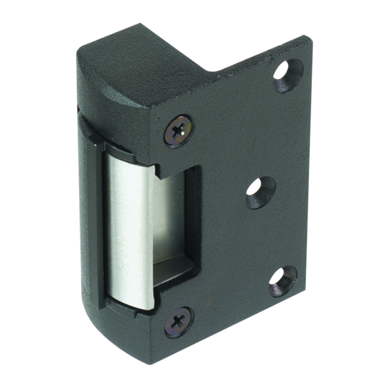
AL150 ELECTRIC
RIM STRIKE
DOOR LATCH POSITION
As shown in Fig.1, there should be a 1mm gap between the door latch and the front face of strike keeper to
prevent the door from exerting pressure on the keeper when door is closed.
MOUNTING STEPS OF STRIKE
1). Position the strikes against the frame, mark and drill the hole sizes as shown on Figure 2 and 3.
2). Drill cable exit hole on door frame.
3). Make sure electrical connections are followed correctly.
4). When the door is closed, ensure that there is no pressure on the front face of strike keeper.
POWER INPUT 12 VDC or 24 VDC SUPPLY:
Note: There's no polarity on power input, AL150 is not equipped with DSS sensor.
INSTALL ON TIMBER DOOR FRAME
Keeper
Figure 1
Figure 2
Door
1mm
Keeper
Door latch
Front face of
strike keeper
Door Frame
5 csk screw
Figure 3
9
12
31
Advertisement
Table of Contents

Related Manuals for alpro AL150


Summary of Contents for alpro AL150
- Page 1 4). When the door is closed, ensure that there is no pressure on the front face of strike keeper. POWER INPUT 12 VDC or 24 VDC SUPPLY: Note: There’s no polarity on power input, AL150 is not equipped with DSS sensor. INSTALL ON TIMBER DOOR FRAME...
- Page 2 CONVERSION: POWER TO LOCK <=> POWER TO OPEN Figure 4A Figure 4B WARNING: Do not press on the keeper to release when the spring screw is not totally secured in position, this will cause damage to the spring barbell. When changing function, micro switch will spring out. Procedures to convert Power to Open (Figure 4B) to Power to Lock (Figure 4A): Step 1: Remove the two cover plate screws.
Need help?
Do you have a question about the AL150 and is the answer not in the manual?
Questions and answers