Advertisement
Quick Links
NS4750-24S-4T-4X-V2 Quick Installation Guide
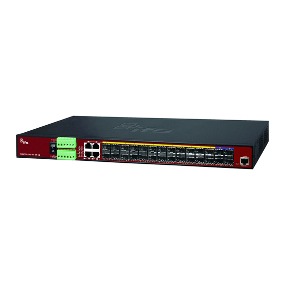
Figure 1: NS4750-24S-4T-4X-V2 L2+ Managed Switch
Package contents
Thank you for purchasing the NS4750-24S-4T-4X-V2 IFS L2+
24-port 100/1000Base-X SFP + 4-port 10G SFP+ L2/L4
managed switch. The descriptions of this model are as follows:
L2+ 24-port 100/1000Base-X managed switch
+ 4-port 10G shared SFP+
Unless specified, the term "managed switch" mentioned in this
quick installation guide refers to the NS4750-24S-4T-4X-V2.
Open the box of the managed switch and carefully unpack it.
The box should contain the following items:
The managed switch × 1
Quick installation guide × 1
RJ45 to RS232 cable × 1
Rubber feet × 4
Two rack-mounting brackets with attachment screws × 1
Power cord ×
RJ45 dust-proof cap × 5
SFP dust-proof cap × 28
If any of these are missing or damaged, contact your dealer
immediately. If possible, retain the carton including the original
packing materials for repacking the product in case there is a
need to return it to us for repair.
Requirements
The managed switch
provides a
management purposes. The following equipment is necessary
for further management:
Workstations running Windows
2008 / 10, MAC OS X or later, Linux, UNIX, or other
platforms are compatible with TCP/IP protocols.
Workstations are installed with Ethernet NIC (Network
Interface Card)
© 2019 United Technologies Corporation.
Interlogix is part of UTC Climate, Controls & Security, a unit of United Technologies Corporation. All rights reserved. All trademarks are the
property of their respective owners. Information in this document is subject to change without notice.
remote login interface for
®
XP / 2003 / Vista / 7 / 8 /
Serial port connection (Terminal)
The above workstations come with a COM Port (DB9)
or USB-to-RS232 converter.
The above workstations have been installed with a
terminal emulator, such as Hyper Terminal included in
Windows XP/2003.
Serial cable – One end is attached to the RS232
serial port, and the other end is attached to the
console port of the managed switch.
Ethernet port connection
Network cables – Use standard network (UTP) cables
with RJ45 connectors.
The above workstations have a Web browser and
JAVA runtime environment plug-in installed.
Note: We recommend using Internet Explorer 11.0 or later to
access the managed switch. If the web interface of the
managed switch is not accessible, turn off the anti-virus
software or firewall and then try it again.
Wiring the power inputs
The front panel of the managed switch contains a terminal
block connector with six contacts. Follow the steps below to
insert the power wire:
1.
Insert the positive/negative DC power wires into contacts 1
and 2 for Power 1, or 5, and 6 for Power 2.
Figure 2: Managed switch front panel
2.
Tighten the wire-clamp screws to prevent the wires from
loosening.
1
2
3
V+
V-
Power 1
P/N 1073619-EN • REV A • ISS 06MAR19
4
5
6
V+
V-
Power 2
Advertisement

Related Manuals for United Technologies Interlogix NS4750-24S-4T-4X-V2


Summary of Contents for United Technologies Interlogix NS4750-24S-4T-4X-V2
- Page 1 P/N 1073619-EN • REV A • ISS 06MAR19 Interlogix is part of UTC Climate, Controls & Security, a unit of United Technologies Corporation. All rights reserved. All trademarks are the property of their respective owners. Information in this document is subject to change without notice.
- Page 2 Figure 4: Console login screen Positive (+) Pin Negative (-) Pin NS4750-24S-4T-4X-V2 Pin 1/5 Pin 2/6 Note: The wire gauge for the terminal block should be in the range from 12 to 24 AWG. Terminal setup Notes: To configure the system, connect a serial cable to a COM port For security purposes, change and memorize the new on a PC or notebook computer and to a RJ45 type serial port password after this first setup.
- Page 3 Store the current switch configuration Figure 9: Login screen At the “#” prompt, type the following command and press Enter. # copy running-config startup-config Figure 7: Saving current configuration command screen Click to begin the process of changing the default If the IP is successfully configured, the managed switch applies username and password.
- Page 4 Refer to the User Manual or click the Help button for further Note: The managed switch security feature requires a change information about using the web management interface. to the default username and password (see “Starting web management” on page 3) after performing a factory reset. We recommend storing your configuration file for upload to the Note: For security purposes, change and memorize the new switch (see “Saving the configuration”...
Need help?
Do you have a question about the Interlogix NS4750-24S-4T-4X-V2 and is the answer not in the manual?
Questions and answers