Table of Contents
Advertisement
Quick Links
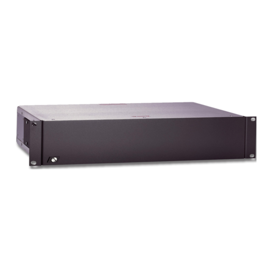
Model AD2096A
Alarm Interface Unit
Installation and Operating Instructions
This manual describes the installation and operating procedures for the American Dynamics AD2096A Alarm Interface Unit.
The AD2096A Alarm Interface Unit, when used with American Dynamics Matrix Switching Systems, automatically calls
specified cameras and preset scenes to specified monitors when contacts are activated external to the system.
-
-
Advertisement
Table of Contents

Summary of Contents for American Dynamics AD2096A
- Page 1 Alarm Interface Unit Installation and Operating Instructions This manual describes the installation and operating procedures for the American Dynamics AD2096A Alarm Interface Unit. The AD2096A Alarm Interface Unit, when used with American Dynamics Matrix Switching Systems, automatically calls specified cameras and preset scenes to specified monitors when contacts are activated external to the system.
- Page 2 The software/firmware furnished with this equipment is confidential to and is copyrighted by SENSORMATIC ELECTRONICS CORPORATION. It is not to be copied or disclosed in any manner without the express written consent of SENSORMATIC. The software/firmware is furnished to the purchaser under a license for use on a single system. Information furnished by SENSORMATIC is believed to be accurate and reliable.
- Page 3 The installation of this product should be made by qualified service personnel and should conform to all local codes. CAUTION RISK OF ELECTRIC SHOCK DO NOT OPEN CAUTION: TO REDUCE THE RISK OF ELECTRIC SHOCK, DO NOT REMOVE COVERS (OR BACK) . NO USER-SERVICEABLE PARTS INSIDE.
-
Page 5: Table Of Contents
Power Sources ... 4 Powering Up ... 4 Alarm Response Operation... 4 Programming Alarm Contacts ... 4 TYPICAL SYSTEM CONNECTIONS AD2096A to AD1650 Series ... C-2 AD2096A to AD1995... C-3 AD2096A to AD1996... C-4 AD2096A to AD2150/2350... C-5 Cascading AD2096A units ... C-6 AD2010DBVL to AD2096A ... -
Page 7: Description
19" rack. • The ears of the AD2096A can be removed and placed such that they are flush with the rear panel. This allows the AD2096A to be mounted to the rear of a rack that is equipped with mounting channels. -
Page 8: Setup
Each group may be set to a different input type. The third switch, S3, is located internally on the AD2096A PC board (see Figure 3), and is used to select the RS-232 COM ports baud rates. -
Page 9: Connections
12-pin connectors into the rear panel connectors. Alarm Relay Output The lower right connector on the rear of the AD2096A is a 12- pin connector which provides access to both Normally-Open (NO) and Normally-Closed (NC) contacts of an internal alarm relay. -
Page 10: Operation
Alarm Response Operation Each alarm input signal is assigned an alarm contact number (ACN) by the AD2096A. The setting of DIP switch S1 (see page 2) determines the range of ACN’s for each AD2096A. Depending on the Matrix Switching System capabilities, a maximum of 1024 alarm contacts (ACN’s) can be programmed... - Page 11 Typical System Connections...
-
Page 13: Typical System Connections Ad2096A To Ad1650 Series
UP TO 7 FEET 6003-0047-02 RS-232 PGM MON TYPICAL AD2096A CONNECTIONS TO AD1650 SWITCHERS: WHEN THE UNITS ARE LESS THAN 7' APART, USE CABLE 6003-0047-02 WHEN DISTANCES EXCEED 7', TERMINAL BOXES MUST BE USED 9 10 11 12 25 26 27 28 29 30... -
Page 14: Ad2096A To Ad1995
55 56 57 58 59 60 61 62 63 64 BROWN (GRD) PORT PORT PORT PORT AD2096A TO AD1995 19 20 21 22 23 24 43 44 45 46 47 48 N N C O C M AD2096A AUX START RELAY OUTPUT TERMINAL BOX 2113-0019-01... -
Page 15: Ad2096A To Ad1996
CABLE 6003-0047-02 FOR DIRECT CONNECTIONS UP TO 7 FEET DATA LINE TYPICAL AD2096A CONNECTIONS TO AD1996 CPU: WHEN THE UNITS ARE LESS THAN 7' APART, USE CABLE 6003-0047-02 WHEN DISTANCES EXCEED 7', TERMINAL BOXES MUST BE USED 9 10 11 12... -
Page 16: Ad2096A To Ad2150/2350
UP TO 7 FEET 2113-0019-01 TERMINAL BOX CAMERAS TYPICAL AD2096A CONNECTIONS TO AD2150/2350 SWITCHERS: WHEN THE UNITS ARE LESS THAN 7' APART, USE CABLE 6003-0047-02 WHEN DISTANCES EXCEED 7', TERMINAL BOXES MUST BE USED 9 10 11 12 13 14 15 16 17 18... -
Page 17: Cascading Ad2096A Units
TYPICAL SYSTEM CONNECTIONS Cascading Multiple AD2096A Units TYPICAL CONNECTIONS TO CASCADE MULTIPLE AD2096A UNITS: WHEN THE UNITS ARE LESS THAN 7' APART, USE MODULAR CABLE 6003-0047-02 WHEN DISTANCES EXCEED 7', TERMINAL BOXES MUST BE USED SELECT ABCDEFGH POWER 25 26 27 28 29 30... - Page 18 OUTPUT CABLE 6003-0047-02 DATA LINE PORTS AD1996 AD2010 Switching Bay TYPICAL SYSTEM CONNECTIONS AD2010DBVL Module to AD2096A to AD1996 18-AWG CABLE 13 14 16 17 18 19 20 21 22 23 24 A A A A A A 43 44 45 46 47 48...
-
Page 19: Index
Index... - Page 21 SPECIFICATIONS ..... . . Rear Cover Wall mounting ........1 AD2096A...
-
Page 23: Declaration Of Conformity
93/68/EEC, and the EMC Directive, 89/339/EEC as amended by 93/68/EEC. Pearl River, NY, USA 15 December, 2000 Harold D. Johnson, Ph.D. Director of Engineering 7, rue Alexis de Tocqueville, Parc de Haute Technologie, 92183 ANTONY CEDEX Alarm Interface Unit AD2096-1 European Contact: Sensormatic France S.A. -
Page 24: Specifications
SPECIFICATIONS Models AD2096A: 120 VAC, 50/60 Hz AD2096-1: 230 VAC, 50/60 Hz Electrical Input: AD2096A AD2096-1 Alarm Inputs Contact Inputs: 64 inputs, each with contact and separate ground Open Circuit Voltage: 5.0 VDC Closed Circuit: Maximum Current: 0.2 mA, Maximum Resistance to Ground: 15K Ohms...


Need help?
Do you have a question about the AD2096A and is the answer not in the manual?
Questions and answers