Table of Contents
Advertisement
Quick Links
Advertisement
Table of Contents

Subscribe to Our Youtube Channel
Related Manuals for Electro-Voice X-Line X1i


Summary of Contents for Electro-Voice X-Line X1i
- Page 1 X‑Line Advance Install X1i | X2i | X12i‑128 User manual...
-
Page 3: Table Of Contents
X-Line Advance Install Table of contents | en Table of contents Important safety instructions Suspension Chlorine Precautions Copyright and disclaimer Symbols Declaration of conformity System overview Dimensions X1i and X2i speaker dimensions X12i subwoofer dimensions Wiring and connections X1i schematic and wiring diagram X2i schematic and wiring diagram X12i-128 schematic and wiring diagram Installing weather plate and gland nuts... -
Page 4: Important Safety Instructions
Any hardware used to suspend a loudspeaker not provided by Electro-Voice is the responsibility of others. Electro-Voice assumes no liability for any damage or personal injury resulting from improper use, installation, or operation of the product. -
Page 5: Chlorine
These Electro-Voice loudspeakers have structural components that use stainless steel. Chlorine can degrade stainless steel over time and reduce its structural performance. Do not use these Electro-Voice loudspeakers in environments with high chlorine content, such as indoor swimming pools. Failure to do so can result in serious injury or death. -
Page 6: Symbols
en | Important safety instructions X-Line Advance Install Symbols Warning! A safety helmet, safety boots, and safety glasses must be used at all times during the installation of the X-Line Advance install system. Failure to do so can result in injury or death. Declaration of conformity Bosch Security Systems Inc. -
Page 7: System Overview
X-Line Advance Install System overview | en System overview The X-Line Advance Install loudspeaker is a premium line-array loudspeaker system designed for high performance permanent install applications, such as sports arenas, houses of worship, and performing arts centers. The system represents a culmination of EV’s extensive experience in designing large format line array systems for touring applications, as well as deep knowledge in designing ruggedized install loudspeaker systems that can survive in harsh, direct exposure environments. - Page 8 en | System overview X-Line Advance Install X1i Passive line array elements Each X1i-212 full-range element consists of one SMX2121 12-inch (304.8 mm) LF driver coupled to a MBH (Mid Band Hydra), and two ND2R 2-inch (50.8 mm) titanium diaphragm HF drivers.
-
Page 9: Dimensions
X-Line Advance Install Dimensions | en Dimensions X1i and X2i speaker dimensions 241.3mm [9.50in] 327.2mm [12.88in] 497.2mm [19.57in] 536.0mm 678.5mm 38.9mm [21.10in] [26.71in] [1.53in] 37.4 mm 79.2mm [1.47in] [3.12in] 186.2mm [7.33in] 309.6mm 267.8mm [12.19in] [10.54in] 347.0mm [13.66in] M10-1.5 THREADED HOLE (8 PLACES) Figure 3.1: X1i dimensions without rigging 245.36mm [9.66in]... - Page 10 en | Dimensions X-Line Advance Install 235.0mm [9.25in] 350.5mm [138.80in] 497.2mm [19.57in] 678.5mm 536.0mm [26.71in] 38.9mm [21.10in] [1.53in] 37.4mm 79.2mm [1.47in] [3.12in] 173.5mm [6.83in] 309.6mm 267.8mm [12.19in] [10.54in] 347.0mm [13.66in] M10-1.5 THREADED HOLE (8 PLACES) Figure 3.3: X2i dimensions without rigging 238.3mm [9.38in] 349.2mm...
-
Page 11: X12I Subwoofer Dimensions
X-Line Advance Install Dimensions | en X12i subwoofer dimensions 713.0mm [28.07in] 123.9mm [4.88in] 336.5mm [13.25in] M10-1.5 THREADED HOLE (16 PLACES) 43.7mm [1.72in] 1050.1mm [41.34in] 713.0mm [28.07in] 1093.7mm [43.06in] 123.9mm [4.88in] 43.7mm 546.9mm 763.5mm [1.72in] [21.53in] [30.06in] 254.8mm [10.03in] 521.1mm 465.9mm [20.51in] [18.34in] 509.5mm... -
Page 12: Wiring And Connections
en | Wiring and connections X-Line Advance Install Wiring and connections X-Line Advance Install loudspeakers utilize heavy duty input panels, with dual 8-conductor Phoenix terminal blocks (Phoenix Contact P/N 1709212). The connectors can accommodate up to 8 AWG stranded wire. Each loudspeaker includes a weather plate and gland nuts to ensure that all electrical contacts are protected from rain. -
Page 13: X12I-128 Schematic And Wiring Diagram
X-Line Advance Install Wiring and connections | en X12i-128 schematic and wiring diagram DVF4180 CONN 1 DVF4180 CONN 2 Bosch Security Systems B.V. User manual 2019.10 | V01 | F01U361103... -
Page 14: Installing Weather Plate And Gland Nuts
en | Wiring and connections X-Line Advance Install Installing weather plate and gland nuts Remove the weather plate and (2) screws (X12i-128 only) from the input panel. X12i-128 Remove the gland nut kit and (2) terminal block connectors from inside the input panel. - Page 15 X-Line Advance Install Wiring and connections | en Connect each wire to the appropriate terminal on the terminal block. Connect the terminal block onto the input connector, and secure in place with the (2) captive screws. Adjust the cable assembly in the cup and tighten the gland nuts.
-
Page 16: Designing An X1I Or X2I Array
There are two methods of deploying X1i and X2i line arrays: With a custom frame, or with the optional Electro-Voice grid and rigging kits. The Electro-Voice grid and rigging kits (sold separately) are a cost-effective method to suspend smaller, simple arrays quickly. One rigging kit is needed for each element in the array. - Page 17 Please see section Custom frame design considerations, page 27 Notice! Electro-Voice has experienced and knowledgeable application engineers willing to assist with any design related questions. Contact information for technical support is located at www.electrovoice.com Bosch Security Systems B.V.
-
Page 18: Designing An X12I-128 Array
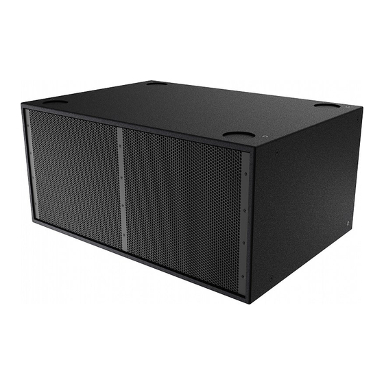
en | Designing an X12i-128 array X-Line Advance Install Designing an X12i-128 array There are 3 methods of installing X12i-128 subwoofers. – Ground stack – Custom frame – Single subwoofer suspended with M10 eyebolts Ground stack subwoofer array X12i-128 subwoofers can be ground stacked using the feet that are included with the subwoofer. - Page 19 X-Line Advance Install Designing an X12i-128 array | en Warning! Do not stack four or more X12i-128 subwoofers horizontally. Never stack two or more X12i-128 subwoofers vertically. Failure to do so can result in injury or death. Use PREVIEW to design the array. Attach feet to bottom of subwoofer.
- Page 20 en | Designing an X12i-128 array X-Line Advance Install Stack subwoofers into the array. The feet from each added subwoofer will fit into the recesses on the subwoofer below. Repeat as necessary to complete the array. 2019.10 | V01 | F01U361103 User manual Bosch Security Systems B.V.
-
Page 21: Custom Frame Example
Qualified professionals must carry out the design, construction, and installation of custom frames, in accordance with applicable laws and regulations. Any hardware used to suspend a loudspeaker not provided by Electro-Voice is the responsibility of others. Standard custom frame Cardioid array in custom frame Warning! Use two or more people to lift and move X12i-128 subwoofers. -
Page 22: Single Subwoofer Suspension Using M10 Eyebolts
en | Designing an X12i-128 array X-Line Advance Install Design the custom frame according the guidelines in Custom frame design considerations, page 27. Single subwoofer suspension using M10 eyebolts X12i-128 indoor and fiberglass models can be suspended individually using the M10 hard points. - Page 23 X-Line Advance Install Designing an X12i-128 array | en Use Electro-Voice EBK-M10-4PACK Eyebolt Kit for proper suspension. Follow the instruction for safe suspension in the EBK-M10 Eyebolt User Instructions, included with the kit. Warning! Always suspend X12i-128 from the top of the enclosure, relative to its orientation. Never suspend an X12i-128 or any other speaker from the bottom of an X12i-128.
-
Page 24: Cardioid Subwoofer Arrays
These arrays can be used to keep bass off of a stage, provide more consistent bass coverage in the audience, or reduce bass in the surrounding area. A cardioid deployment requires at least two X12i-128 subwoofers. Electro-Voice provides optimized DSP speaker settings for the X12i-128 in cardioid configurations. These settings can be implemented in hardware controlled by SONICUE or IRIS-Net software. - Page 25 X-Line Advance Install Designing an X12i-128 array | en Cardioid option A: Two X12i-128 subwoofers orientated horizontally. Direct the top subwoofer towards the audience and the bottom subwoofer away from the audience. Cardioid option B: Three X12i-128 subwoofers orientated horizontally. For ground stack applications, direct the top two subwoofers towards the audience and the bottom subwoofer away from the audience.
-
Page 26: Drain Holes
In applications where the X12i-128 is located in an environment with direct rain exposure, Electro-Voice recommends that the drain holes are used. Notice! Opening the drain holes may cause minor air noises close to the subwoofer that will be inaudible at normal listening distances. -
Page 27: Custom Frame Design Considerations
Only certified structural engineers should be used to design any custom suspension frame. Failure to do so could result in serious injury or death. Warning! Any hardware used to suspend a loudspeaker array not associated with Electro-Voice is the responsibility of others. Warning! The simplified designs shown are for illustrative purposes only and do not represent or imply a complete design from Electro-Voice. - Page 28 en | Custom frame design considerations X-Line Advance Install Use all eight M10 structural hard points on DO NOT use only some of the M10 hard the loudspeaker element, four on each side of points. the element. DO NOT modify the loudspeaker to add a custom hard point.
- Page 29 X-Line Advance Install Custom frame design considerations | en Use M10 fasteners that penetrate the DO NOT use fasteners that are too long or loudspeaker element 30 - 45 mm (1.2 - 1.8 too short. in). Use thread locker and appropriate torque for the type of fastener used.
-
Page 30: Notes
en | Notes X-Line Advance Install Notes 2019.10 | V01 | F01U361103 User manual Bosch Security Systems B.V. - Page 32 Bosch Sicherheitssysteme GmbH Bosch Security Systems, Inc Robert-Bosch-Ring 5 12000 Portland Avenue South 85630 Grasbrunn Burnsville MN 55337 Germany www.boschsecurity.com www.electrovoice.com © Bosch Sicherheitssysteme GmbH, 2019 © Bosch Security Systems, Inc., 2019...
Need help?
Do you have a question about the X-Line X1i and is the answer not in the manual?
Questions and answers