Table of Contents
Advertisement
Quick Links
Advertisement
Table of Contents

Related Manuals for bolid IPR 513-3M


Summary of Contents for bolid IPR 513-3M
- Page 1 CONVENTIONAL MANUAL CALL POINT IPR 513-3M User’s Manual...
-
Page 2: Table Of Contents
Table of Contents Description and Operation ....................4 1.1 Purpose..........................4 1.2 Specifications ........................5 1.3 Scope of Delivery ......................6 1.4 Design and Operation ....................... 6 1.5 Measuring Instruments, Tools, and Accessories ..............7 1.6 Marking and Sealing ......................7 1.7 Packaging ......................... - Page 3 This user’s manual explains the principles of operating IPR 513-3M Conventional Manual Call Point (hereinafter referred to as the MCP, equipment, or product). Only the personnel who have studied this manual are allowed to operation activities. All activities on mounting, programming and commissioning shall be performed in compliance with the requirements of the regulatory documentation in force at the place of operation.
-
Page 4: Description And Operation
1 Description and Operation Purpose IPR 513-3M Conventional Manual Call Point (hereinafter referred to as the MCP) is to be used in fire detection and fire alarm systems for manual initiation of fire alarm signals. It operates in an alarm loop of control and indicating equipment S2000-4, Signal-20P, S2000- ASPT, Signal-10, Signal-20М... -
Page 5: Specifications
10 years 1.2.18 Expected lifetime 1.2.19 As to immunity to electromagnetic interference, the IPR 513-3M meets the requirements of Test Severity Level III as per the relevant standards listed in Annex B to GOST R 53325-2012. 1.2.20 The IPR 513-3M passes the industrial interference standards prescribed for Class B equipment per... -
Page 6: Scope Of Delivery
Scope of Delivery Table 1.3.1 represents the content of MCP standard delivery Table 1.3.1 Item Quantity IPR 513-3M Conventional Manual Call Point 10 pcs. Accessory Kit: Special housing key 10 pcs. 20 pcs. Screw 1-4×30.20.019 GOST 1144-80 20 pcs. Wall plug 8×30... -
Page 7: Measuring Instruments, Tools, And Accessories
Pliers 160 mm Marking and Sealing Every IPR 513-3M has a marking placed inside its housing on the rear panel shown in Figure 2.2.2.2. The marking contains the name of the product, its decimal number, factory number, the year and quarter of production, and conformity marks. -
Page 8: Intended Use
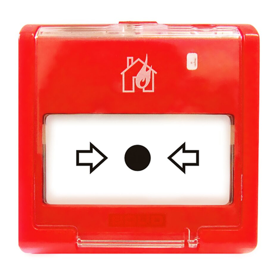
– Mounting and maintenance of the MCP should be carried out by persons with the second or higher electric safety qualification level. 2.2.2 Design The IPR 513-3M appearance is shown in Figure 2.2.2.1. Overall Dimensions are 95 mm × 91 mm × 34 mm. Figure 2.2.2.1. IPR 513-3M View The rear panel of the MCP with the mounting dimensions is represented in Figure 2.2.2.2. -
Page 9: Mounting
Figure 2.2.2.2 Mounting Dimensions for the MCP 2.2.3 Mounting The MCP is to be mounted to a flat vertical surface in line with Buildings Codes and Regulations. The MCP rear panel (base) is attached to the wall with two screws. The front part of the housing is installed on the mounted base after connecting wires to the terminal block. -
Page 10: Wiring
2.2.4 Wiring Figure 2.2.4.1 represents a typical schematic for wiring the MCP. Wire the MCP in line with the operation documentation for the control and indicating unit (device) in use and the connection diagrams shown in this documentation. 1: Control and Indicating Unit (Device), 2, 3: MCP, 4: An end-of-line device (resistor, diode, etc.). -
Page 11: Troubleshooting
2.2.9 Troubleshooting Table 2.2.9.1 Fault Possible Cause Solution The indicator is off No power applied Check the voltage at the MCP contacts “+” and “–“; in case of zero voltage check the integrity of cables and contact joints No fire alarm after No communications between the Check the integrity of cable and pressing the operating... -
Page 12: Maintenance
3 Maintenance General The equipment is to be serviced according to a scheduled-preventive system, which provides annual maintenance. Safety Precautions The MCP should be maintained by personnel qualified for the Electrical Safety of Level II or higher. Maintenance Schedule Scheduled maintenance works include checks defined in Table 3.3.1. Table 3.3.1 Quarter Quarter... -
Page 13: Technical Examination
Technical Examination Technical examination is not applicable for this equipment. Preservation (Depreservation, Represervation) Preservation is not applicable for this equipment. -
Page 14: Routine Repair
An equipment failure resulted from consumer’s not observing rules of mounting and operation is not a reason for claims and warranty repair. Claims shall be submitted to the following address: NVP BOLID, #4 Pionerskaya Str., Korolyov, Moscow Region, 141070, Russia. Tel./fax: +7 (495) 775-71-55 (PBX). E-mail: info@bolid.ru. -
Page 15: Certification Information
TR EAEU 037/2016 “On the restriction of the use of hazardous substances in electronic and radio electronic equipment” and is covered by Conf. Declaration ЕАЭС № RU Д-RU.РА01.В.82301/19. The production of IPR 513-3M Conventional Manual Call Point is awarded with Conformity Certificate GOST R ISO 9001. The Certificate is available on the website https://bolid.ru...
Need help?
Do you have a question about the IPR 513-3M and is the answer not in the manual?
Questions and answers