Table of Contents

Subscribe to Our Youtube Channel
Related Manuals for bolid UO-4S Revision 02


Summary of Contents for bolid UO-4S Revision 02
- Page 1 Orion ISS GSM Four-Input Alarm Panel UO-4S Rev.02 User’s Manual The Bolid Company, Russia; 4 Pionerskaya Str., Korolev, Moscow Region 141070 Tel./Fax: +7 (495) 775-71-55 (PBX), 777-40-20, 516-93-72 info@bolid.ru, http://bolid.ru E-mail:...
- Page 2 This User’s Manual is intended to help for studying operability and maintenance principles of UO-4S Revision 02 GSM Four-Input Alarm Panel. Please read the instructions from this manual completely before connecting, adjusting, oper- ating, or maintaining this device The following terms are used throughout the Manual: Alarm Loop: The electrical circuit with non-addressable fire or intrusion detectors (or other non- addressable devices) included.
-
Page 3: Table Of Contents
Table of Contents General ..............................5 Specifications ............................6 Standard Delivery ..........................7 Operation Principles .......................... 8 General Layout and Main Functions ..................8 Operation Modes ........................9 Indication ..........................11 Alarm Loops ......................... 13 Relay Control ........................14 Credential Programming Mode ..................... 15 Arming and Disarming by means of Dallas iButtons .............. - Page 4 Appendix A. Contact ID Protocol ..................46 Appendix B. User’s SMS ...................... 48 Appendix C. Egida-2 SMS ....................49 Appendix D. Egida-3 SMS ....................50 Appendix E. Voice Messages ....................53 Manufacturer Data .......................... 54...
-
Page 5: General
GENERAL UO-4S Revision 02 GSM Four-Input Alarm Panel (hereinafter referred to as the UO-4S or the panel) is designed to be used in centralized and standalone intrusion and fire alarm systems for industrial, business, and residential premises (enterprises, banks, offices, hospitals, shops, warehouses, residential buildings, etc.). -
Page 6: Specifications
SPECIFICATIONS Alarm Inputs (Alarm Loops) 4 Initiating Device Circuits Input voltage in the quiescent mode 6 to 12 V Integration Time 300 ms Max current drawing through an alarm loop 12 mA Max resistance of wires without regards to termination 1 kOhm for intrusion alarm loops, resistance 100 Ohm for fire alarm loops... -
Page 7: Standard Delivery
STANDARD DELIVERY Item Q-ty UO-4S Revision 02 GSM Four-Input Alarm Panel 1 pc. Antenna 1 pc. Installation Manual 1 pc. Datasheet 1 pc. iButton 1 pc. Half-round head woods screw 3×25 3 pcs. Wall plug 6х30 S 3 pcs. DIN 7982 flat head tapping screw with cross drive 2.2×6.5 1 pc. -
Page 8: Operation Principles
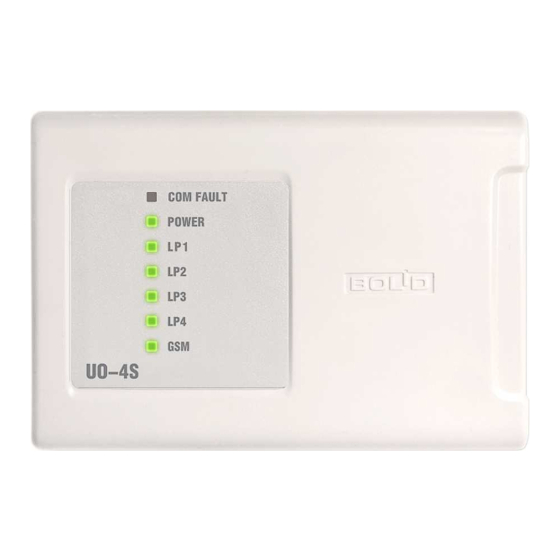
OPERATION PRINCIPLES GENERAL LAYOUT AND MAIN FUNCTIONS Figure 1. UO-4S Layout The UO-4S comprises the following hardware elements: • Tamper switch; • Beeper; • Seven information LEDs; • XР2 Mode Select jumper; • XР3 620 Ohm pull-up resistor jumper; • Two slots for primary (the lower one) and backup SIM cards; •... -
Page 9: Operation Modes
• Transmits notifications through GSM 900/1800 cellular communication channels providing backup operation (the second SIM card). • Provides transmitting to five phone numbers with programming the following notification types for every phone number: o Contact ID (ADEMCO), o User SMS, o Egida-2 SMS, o Egida-3 SMS, o CSD,... - Page 10 Slave 1, Slave 2 This mode is in use when the UO-4S operates as part of Orion integrated security system under an S2000 or S2000M monitoring and control panel. Transmitting notifications via UO-4S is supported by S2000 panels of versions 1.12+ and all versions of S2000M panels.
-
Page 11: Indication
When the UO-4S operates in the Master mode the numbers of all the alarm loops and readers and the addresses of the devices must be enrolled on the Zones and Partitions tab of UProg. Every string number of this tab is considered as the Contact ID number of the zone, reader, or device which is described in this string. - Page 12 Table 2. Internal Beeper Event (Condition) Beeper Performance Norm Alarm, Fire Interrupted sound (Can be enabled / disabled via UProg) Short/Open Circuit Failure Beeps once per second Two beeps upon arming Arming (Can be enabled/disabled by means of UProg) Turns off (if it was on) and then beeps once Disarming (Can be enabled/disabled by means of UProg) Beeps once per two seconds...
-
Page 13: Alarm Loops
The parameter Disable Device Indication in UProg provides disabling of almost all UO-4S indication except for the GSM indicator. If this parameter is set on then the panel regardless of its operation mode doesn’t indicate by sound or by light conditions of its own alarm loops, communication conditions, power conditions, and reading iButtons. -
Page 14: Relay Control
Table 4 Loop State Depending on the Loop Resistance Loop Type Activated Open Failure Short Failure 17 k÷50 k <200 Ω Fire >50 k 2÷14 k 500 Ω÷1,6 k Intrusion, <1.6 k 2÷14 k ------------ ---------------- Panic, Entrance >17 k For the purpose of protection against sabotage, after the intrusion alarm loops are armed they are monitored for changes their resistance with time. -
Page 15: Credential Programming Mode
Table 5 (continued) Tactics «Alarm Output» ** All the alarm loops are armed Otherwise Tactics «Switch Off upon Arming»*** A command to arm the alarm loop is given The relay is turned off for a time Otherwise The relay is turned on Tactics «Remote Control»... - Page 16 7. Quitting the mode of programming the Master Key is performed by short closing the reader contacts for 4 seconds or automatically in 30 seconds after completing configuring operation. In this case the panel issues one beep and then one long sound signal. Quitting can also be performed by shutting the power off.
-
Page 17: Arming And Disarming By Means Of Dallas Ibuttons
3. Holding the Master Key touched to the reader press the tamper switch (see Figure 1) down for a short time (no longer than 0.5 s) and then remove the Master Key. POWER LED shall flicker periodically (two times per second with pauses of 1 second) indicating the mode of deleting credentials. -
Page 18: Controlling Uo-4S Remotely By Sms
CONTROLLING UO-4S REMOTELY BY SMS To control the UO-4S remotely it is necessary to send an SMS with a relevant command to the UO-4S phone number (the phone number of the currently active SIM card) – see Table 7. Table 7. Remote Control Commands Commands SMS Messages Request for Armed Loops... -
Page 19: Inspecting Panel Operation In The Test Mode
ance can be checked among others also for post-paid cards (in this case and answer can be received in two parts namely as a USSD message about receiving a request and an SMS with the balance status). If no response has been received for account balance requests then you need to change SMS notification service to USSD. -
Page 20: Transmitting Notifications
– The panel beeps; – The indicators COM FAULT, POWER, LP1 - LP4 1. Illuminate with amber, then 2. Illuminate with green, then 3. Illuminate with red, then 4. One-by-one turns on with green, and finally 5. One-by-one turns on with red. After the test has been completed the panel automatically exits the self-diagnostic mode and returns to quiescent mode. - Page 21 SMS (Egida-2), SMS (Egida-3) Transmitting SMS to a central monitoring station with Egida rev.02 or Egida rev.03 software respectively. Notification formats are shown in Appendix C and Appendix D. Receivers can be an UOP-3 GSM and a GSM modem. Description of SMS for the protocols Egida-2 and Egida-3 is not available for editing by user.
- Page 22 Testing Communication Channel Test notifications are intended for testing current operability of the communication channel and can be applied for phone 1 and phone 2. A Test notification can be either SMS (a transmission period in hours should be specified) or a phone call (a call period can be set in minutes or in hours or a time for calls once or twice a day should be specified).
-
Page 23: Mounting
MOUNTING MOUNTING THE DEVICE Figure 2 shows the appearance and overall and mounting dimensions of the UO-4S panel. The panel is to be mounted on walls or other structures in the premises at places protected against atmospheric fallouts, mechanical damage, and unauthorized access. Wiring of connecting lines is to be carried out as shown in Figure 5 (“UO-4S Connection Diagram”). - Page 24 Mounting on a Wall 1. Please ensure that the wall the device is to be mounted on Выкрутите винт Unscrew the screw крепления крышки fixing the cover is solid, flat, clean, and dry. 2. Mark places for three mounting holes on the wall (for two Push the top end Нажмите...
- Page 25 RS-485 Interface Bus When the UO-4S is used as part of an Orion integrated security system: 1. Connect the terminals RS-485A and RS-485B to the lines A and B of the RS-485 interface bus respectively. 2. Connect the “0 В” circuit of the panel to the similar circuit of the preceding and the subsequent devices on the RS-485 trunk (if the devices are powered by the same power supply this doesn’t have to be done).
- Page 26 Four-wire detectors (with external powering) should be used as fire detectors. After receiving a Fire event it is necessary to reset power of the relevant detector; for doing so one of the panel relay outputs can be used (the tactics «Switch Off upon Arming»).
-
Page 27: Programming
To configure the UO-4S parameters, connect the panel to a power supply and to a PC with UProg.exe Device Configuration Tool installed via the adapter cable provided or via one of the Bolid manufactured interface converters (PI-GR, S2000-PI, S2000-USB, or USB-RS-485). -
Page 28: Running Configuration Tool
Please remove SIM-cards from the UO-4S while programming the panel parameters. The XP2 jumper (see Figure 5) must be closed during programming. RUNNING CONFIGURATION TOOL Run UProg. Load configuration from the device memory: → → → → Menu Device Read Device Configuration The window for searching devices connected to the computer appears on the PC display. -
Page 29: Tab «Device
Tab «Device» Figure 12. UProg for UO-4S Object • Object number is composed of four digits 1 to 9. • Object Name can comprise maximum 64 Latin characters including spaces or 32 characters including spaces if Cyrillic characters are in use (used in case of transmitting user SMS). •... - Page 30 Device • Operation Mode: This parameter provides selecting the mode of panel operation. The required operation mode must be obligatory selected prior to proceeding to set- ting parameters of credentials, zones, and partitions. • Use Backup SIM Card: If a second (backup) SIM card is installed into the UO-4S then when a notification cannot be transmitted over the primary notification channel (poor communication quality, zero or negative account balance) this one will be transmitted over the backup communication channel (both cards are equivalent and the panel returns to operation with the...
- Page 31 Relay Outputs To program relays it is necessary to select Relay Type, to give Activation Time during which every relay is activated in accordance with the defined control tactics, and to select the alarm loops linked with every relay. The parameter Activation Time for the relay tactics Switch Off upon Arming can be set to a value which corresponds to a time in the range of 1 to 10 seconds, with one unit of the parameter being equal to 0.125 s.
-
Page 32: Tab «Alarm Loops
Tab «Alarm Loops» Figure 14. Alarm Loops Tab Auto Arming Delay: This parameter means a time in which an alarm loop will be armed when it has been repaired after being in alarm. The value can be set in the range of 1 to 255. For an alarm loop of the Entrance type Auto Arming Delay must exceed Entry Delay. -
Page 33: Tab «Telephones
Tab «Telephones» Figure 15. Telephones Tab Voice Message Transmission Attempts A communication attempt can fail due to subscriber on the receiving side being busy or poor link quality or a communication failure. After a specified number of attempts the panel proceeds to a next subscriber and enter the communication fault mode for the current subscriber. - Page 34 Listen Timeout in 10 s-Intervals (*10) It is the time after expiry of which the panel terminates the connection established upon activation of an alarm loop of the Phone Call type. Phone Number A phone number should be entered completely including the country/area code (the prefix «+» can be used).
- Page 35 The field Test Transmission Period can take a value ranging or from 1 to 59 if the period is set in minutes, or from 1 to 24 if the period is set in hours or at a specified time, or from 1 to 12 when the Twice a Day flag is set on.
-
Page 36: Tab «Message Filter
Tab «Message Filter» Figure 16. Message Filter Message Filter provides adjusting a list of events and local alarm loops for which notifications will be sent to a specified phone. A tick in the Message Filter table means transmitting the relevant messages to the relevant phone while a blank cell means that the events will not be transmitted. -
Page 37: Tab «Credentials
Filter Name Events Armed Partition is armed, a leakage is repaired Alarm Intrusion alarm, panic alarm, leakage (flood detector alarm) Fire Fire, Fire2 Alarm loop short circuit failure, alarm loop open circuit failure, fire Loop Failure protection equipment failure, service required, loop configuration error, temperature sensor fault, noise Communications Restored Communication with the device/subscriber is restored... - Page 38 Enrolling Credentials by means of an iButton Reader To enroll credential codes by means of an iButton reader, the iButton reader should be connected to the UO-4S terminals 23, 24, and 25 (see Figure 5). 1. Load the panel configuration by means of UProg. Go to the Credentials tab. When the Cre- dential tab has been open the device descriptors start being read from the panel memory au- tomatically.
- Page 39 The credential with ID 0 is the system Master Key which is used for programming user credentials for the UO-4S without UProg and cannot be used for arming / disarming. In the modes Slave 1 and Slave 2 all the credentials including local ones must be enrolled in the control panel.
-
Page 40: Tab «Zones And Partitions
Tab «Zones and Partitions» Standalone Mode: The match between the zones and partitions is given in the UO-4S. A Zone Number means the number of an ID Contact Zone (in the Standalone mode this tab can be not filled in). Master Mode: The match between device addresses, zones, and partitions is described in the UO-4S. -
Page 41: Tab «Message Descriptors
Tab «Message Descriptors» Figure 20. Message Descriptors This tab is intended to edit texts of user SMS if necessary. Symbols in Latin or Cyrillic scripts can be used. The SMS writing system can be selected from the context menu by right clicking on a text string. -
Page 42: Tab «Gprs Settings
Tab «GPRS Settings» Figure 21. GPRS Settings Enable GPRS: The flag enables sending data over the GPRS channel. For the main and backup receiver the following parameters must be set individually: • IP Address (Static IP address of the host with Egida rev.3 Central Monitoring Station) •... - Page 43 Also your own encryption key can be generated by the program automatically using the typed passphrase. For doing so, enter a password in Latin script into the Password field, then confirm it, and finally save changes by clicking OK. For Egida 3 Central Monitoring Station the same password must be entered in GPRS settings for this UO-4S to provide decoding of the notifications.
-
Page 44: Maintenance
MAINTENANCE The UO-4S must be maintained at least annually by electricians with the third or higher electric safety qualification level. To maintain the panel, do the following: a) Ensure the panel enclosure is not damaged and is mounted securely; ensure the wire terminals are fastened properly;... -
Page 45: Storage, Transportation, And Warranty
The warranty period is 18 months since putting the panel into operation, but no more than 24 months since the acceptance date. In case of difficulties in programming or operating the product, please contact Technical Support by calling +7 495 775-71-55 (multichannel) or by emailing support@bolid.ru. -
Page 46: Appendices
APPENDICES APPENDIX A. CONTACT ID PROTOCOL Contact ID Protocol Messages Partition Serial Zone Number (Z), Number Notification Number User ID Event Qualifier Code 2 sym- 4 symbols 3 symbols bols Disarmed XXXX Р User Р Armed XXXX User XXXX Р Arming Failed XXXX Guessing... - Page 47 Contact ID Protocol Messages Partition Serial Zone Number (Z), Number Notification Number User ID Event Qualifier Code 2 sym- 4 symbols 3 symbols bols XXXX Р Auxiliary Loop Alarm (Orion) Р Auxiliary Loop Restored (Orion) XXXX XXXX Р Low Battery (Orion) Р...
-
Page 48: Appendix B. User's Sms
APPENDIX B. USER’S SMS Default Notification List Notification In Latin In Cyrillic Disarmed DISARMED СНЯТ Armed ARMED ВЗЯТ Arming Failed FAULT НЕВЗЯТ Wrong Code (is generated after presenting REFUSE ДОСТУП ОТКЛОНЕН three unknown credentials) ОТМЕТКА НАРЯДА Patrol Check DETAIL Alarm Loop Open Circuit Failure BREAK ОБРЫВ... -
Page 49: Appendix C. Egida-2 Sms
APPENDIX C. EGIDA-2 SMS Egida-2 Egida-2 Notification Local Mode Slave 1/2, Master Mode Disarmed DISARMED S USER N DISARMED PART P USER N Armed ARMED S USER N ARMED PART P USER N Arming Failed FAULT S FAULT PART P ZONA Z Wrong Code (is generated after presenting three REFUSE... -
Page 50: Appendix D. Egida-3 Sms
APPENDIX D. EGIDA-3 SMS Notification Event Source Disarmed F99 IXXXX M242 Partition/UO-4S Internal Alarm Loop Armed F99 IXXXX M241 Partition/UO-4S Internal Alarm Loop Arming Failed F99 IXXXX M17 Zone/UO-4S Internal Alarm Loop Wrong Code F99 IXXXX M26 Reader Patrol Check F99 IXXXX M223 UO-4S Open Circuit Failure... - Page 51 Notification Event Source Normal Temperature F99 IXXXX M78 Zone High Level F99 IXXXX M74 Zone Low Level F99 IXXXX M71 Zone Too High Level F99 IXXXX M75 Zone Too Low Level F99 IXXXX M77 Zone Normal Level F99 IXXXX M72 Zone Auxiliary Input Alarm F99 IXXXX M35...
- Page 52 Notification Event Source Inhibited (Orion) F99 IXXXX M147 Zone F99 IXXXX M143 Zone Abort (Orion) F99 IXXXX M221 Zone Pressure Switch Failed (Orion) Pressure Signal (Orion) F99 IXXXX M220 Zone F99 IXXXX M141 Zone Pre-Discharge Delay (Orion) F99 IXXXX M144 Zone Released (Orion) Fire 2 Alarm (Orion)
-
Page 53: Appendix E. Voice Messages
APPENDIX E. VOICE MESSAGES List of Default Voice Messages Notification Voice Message Снят с охраны раздел P пользователь N Disarmed Armed Взятие под охрану раздел P пользователь N Не взятие раздел P зона Z [пользователь N] Arming Failed Wrong Code Доступ... -
Page 54: Manufacturer Data
MANUFACTURER DATA Made by the Bolid Company, Russia. 4 Pionerskaya Str., Korolev, Moscow Oblast, 141070, Russia Tel./Fax: +7 (495) 775-71-55 (multichannel), 777-40-20, 516-93-72 E-mail: http:// info@bolid.ru, bolid.ru. Technical Support: support@bolid.ru.
Need help?
Do you have a question about the UO-4S Revision 02 and is the answer not in the manual?
Questions and answers