Table of Contents

Related Manuals for Mattei AC 6000 Series


Summary of Contents for Mattei AC 6000 Series
- Page 1 AIR COMPRESSORS INSTRUCTION, USE AND MAINTENANCE MANUAL TI008G0001 ING. ENEA MATTEI Strada Padana Superiore 307 - 20090 VIMODRONE (MI) Tel +39 - 02253051 (16 linee) - Fax +39 - 0225305243 E-Mail: info@mattei.it - www.matteiaircompressors.com...
- Page 2 The content of this document cannot be used, reproduced or disclosed to third parties without the explicit written consent of Ing. ENEA MATTEI S.p.A. Ing. ENEA MATTEI S.p.A. reserves the right to modify the characteristics of the machine subject of this document without prior notice.
- Page 3 General Index 0.01 General Information - Symbols in the manual Page 1.01 - Purpose of Document Page 1.02 - Required Qualifications for Operators Page 1.03 - Identification data of the Manufacturer and the Machine and the location of the nameplate “CE MARKING” Page 1.04 - General Delivery Notes - Final inspection - General Safety Warnings Page 1.05...
-
Page 4: General Information
General Information 1.01 Symbols in the manual In this manual some symbols are used that to attract the reader’s attention and underline some particu- larly important aspects of the treatment. The table below gives the list and describes the meaning of the different symbols used. SYMBOL MEANING and NOTES Danger... - Page 5 The machine has been designed, made, and inspected in compliance with the “safety and health es- sential requirements” stated in attachment I to the European Directive 98/37/EEC. The list below gives the reference Standards used by Ing. ENEA MATTEI S.p.A. to design, make, and to make the final inspection of the machine.
- Page 6 General Information 1.03 Required Qualifications for Operators The operator in charge of the operation or the maintenance of the machine should have all the profes- sional requirements specific to each foreseen operation. The operator should be trained and aware of his responsibilities. Below is the description of the professional profiles concerning the operators in charge of the machine Entry Level Machine Operator (Qualification 1) Qualified staff able to carry out simple tasks, i.e.
- Page 7 Identification data of the Manufacturer and the Machine and the location of the nameplate “CE MARKING” Ing. ENEA MATTEI S.p.A. is identified as the machine’s manufacturer in conformity with the laws in force with the following acts: - Declaration of conformity - CE Marking – Instruction Manual...
-
Page 8: General Notes On Delivery
Ing. ENEA MATTEI S.p.A. is responsible for the machine under its original configuration. Ing. ENEA MATTEI S.p.A. refuses any responsibility for improper use of the machine, for damages due to operations which are not described in this manual or unreasonable jobs. -
Page 9: Installation
General Information 1.06 Authorized staff Authorized staff means personnel duly trained and appointed to perform the activities listed below and that make up the operating instructions for the machine. Appointed staff Appointed staff means the personnel who, although not participating materially in the work, supervise the work of others, for example the responsible engineer. - Page 10 General Information 1.07 Installation and commissioning “The installation and commissioning are only permitted to authorised staff. During installation, handle the machine components as indicated in this manual; if lifting is necessary, verify first the correct fixing of specific devices for lifting and use adequate slings and equipment. The machine installation should be as free as possible from any material preventing or limiting its view.
- Page 11 General Information 1.08 Decommissioning and dismantling Only authorised staff is allowed to decommission and remove the machine. Before setting the machine out of operation it is necessary to disconnect the mains isolator and block it in the open position. Discharge oils and fluids, remove all moving parts. Disconnect the mains isolator cable, by cutting out the power wires and then the earth wire.
- Page 12 General Information 1.09 Settings to be made by customer Unless different contractual agreements are taken, the following items are normally at customer’s ex- pense: ❑ room preparation (including building works, such as foundations or canalizations, etc, if required); ❑ anti-slip, levelled flooring; ❑...
- Page 13 General Information 1.10 For any kind of information on the use, maintenance, installation, etc. Ing. ENEA MATTEI S.p.A. is always available to meet the Purchaser’s requests. However, any enquiry should be made in clear terms, with references to this manual and always stating the data on the machine id plate.
-
Page 14: General Information - Safety
General Information - Safety 2.01 To operate the machine under any operating condition, including maintenance, it is not necessary that more than one person be present. Using more than one person is superfluous and, in any case, not allowed for safety reasons. - Page 15 General Information - Safety 2.02 After having carefully considered all possible risks concerning the use and maintenance of the machine, all measures have been adopted to eliminate risks and limit dangers to exposed people. Although the machine is equipped with safety devices, the following residual risks remain, which can be eliminated or reduced by the relevant precaution: •...
- Page 16 For cleaning DO NOT USE flammable fluids or products not complying with current regulations. In case of doubts about the compressor operation or of any of its components, it is recommended to contact the after sales service of Ing. Enea Mattei S.p.A. The following should be also considered: ❑...
- Page 17 General Information - Safety 2.04 Responsibilities Ing. Enea MATTEI S.p.A. refuses any responsibility for injuries to people, animals or damages to objects, caused by: ❑ non-observance of the mentioned precautions; ❑ improper use of compressed air or of the machine in general;...
- Page 18 General Information - Safety 2.05 Description of Pictograms Pictograms have been applied on the machine to explain following situations: Danger Obligation Prohibition Special indications (example: direction of rotation of the fan, etc) Many accidents are often caused by the non- observance of the simplest safety rules or poor knowledge of the instructions given by the manu- facturer.
- Page 19 General Information - Safety 2.06 Description of Pictograms Obligation pictograms These are circular signs on a blue background, and the symbol is white. Read the instructions manual before carrying out any operation on the machine. Use individual protective means against noise. Indication pictograms These signs may vary in shape and they give useful information.
-
Page 20: Description Of The Machine
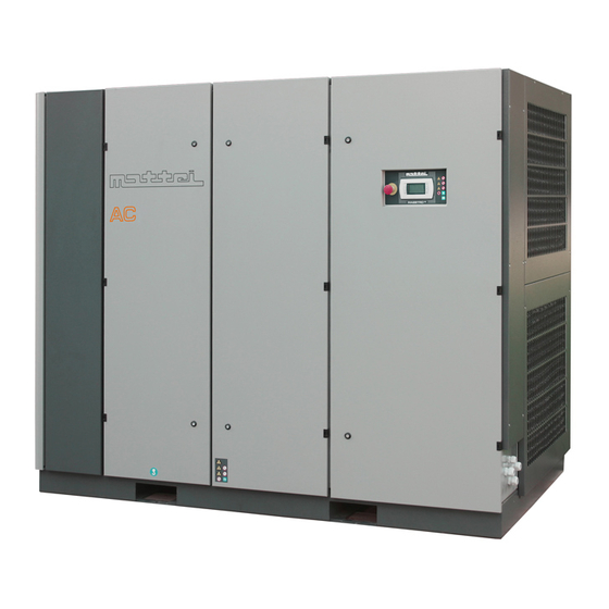
Description of the Machine 3.01 Mattei rotary compressors of the AC Series are the result of over 80 years of investments in research and development, to improve performance continuously, and at the same be environment-friendly. The modulation operating mode is not available for compressors of the AC 6000 series. - Page 21 Description of the Machine 3.02 All components are enclosed in a soundproofing canopy in sheet stell , epoxy powder painted and lined with deadening fire-resistant material. The canopy has a pre-filter to prevent intake of gross particles that might prematurely clog the radiators and air filter.
-
Page 22: Cooling Systems
Description of the Machine 3.03 Minimum pressure and non return valve Compressed air is delivered by the compressor through a valve ensuring a minimum pressure inside the oil chamber, so as to gua- rantee smooth operation when the compressor is delivering air. This valve also prevents the compressed air in the system from returning to the compressor. - Page 23 Description of the Machine 3.04 Separator receiver The receiver is supplied with an INSTRUCTION, USE AND MAIN- TENANCE MANUAL which must be kept and consulted before use, and with a DECLARATION OF CONFORMITY clearly indicating the main technical data and the operating limits. The receiver is built to contain compressed air and oil;...
- Page 24 Description of the Machine 3.05 MAESTRO is a programmable control unit which adapts compressor operation to the specific requirements of the air line it is con- nected to. It features various programming levels and performs operating and fault con- trols and analysis. Advanced programming and analysis levels are protected by digital codes to prevent unin- tentional access.
- Page 25 ❏ Running compressor (optional) ❏ Compressor under load (optional) ❏ Compressor blocked (standard) Communication MAESTRO , connected to the Mattei supervision device (optional), allows for: Remote monitoring by web interface Alarm signaling by e-mail, fax or mobile phone. WARNING !!! The compressor has been designed to compress AIR ONLY.
- Page 26 1 Electrical Diagram (inside the control board) Documents for the optional accessories CERTIFICATIONS Ing.Enea Mattei SpA has its company quality system certified according to standard UNI EN ISO 9001 by DNV while the final inspection procedures comply with standard ISO 1217 and have been certified by TÜV.
-
Page 27: Operating Mode
Description of the Machine 3.08 Built-in Dryer (versions plus) Each AC unit (OPTIMA / MAXIMA) is supplied with a compressed air cooling radiator. Cooling produces condensation that is unload- ed from specific separators and drainpipes that can be applied on the front of the machine (see this section Optional Accessories). - Page 28 NOTE: The user can request Ing. ENEA MATTEI that the fault in the dryer corresponds to a machine BLOCK. NOTE: The design of the dryer prevents condensate from accumulating and ice from forming inside it.
- Page 29 Description of the Machine 3.10 Position of main parts 1 - Compressor �� 2 - Intake filter �� 3 - Electric starter � 4 - Oil cooler � 5 - Air cooler 6 - Oil drain � � 7 - Receiver/Final oil separator ��...
- Page 30 Description of the Machine 3.11 Technical Data and Overall Dimensions TI008G0001...
- Page 31 Transportation and handling 4.01 The whole area for the machine handling, including the space between the parking area for transport means and the machine installing area should be identified and inspected beforehand, to find any possible "DANGEROUS AREAS". Be careful when handling, lifting and transporting the machine, not to damage it and not to damage things or cause injuries to persons.
-
Page 32: Installation
An air-cooled compressor,driven by an electrical motor,produces heat equal to about 85% the absorbed power. For the AC 6000 Series machines,having the cooling air outlet on the canopy top panel, the di- stance from the ceiling should not be lower than 1,5 meters. - Page 33 Installation 4.03 Electrical connection Only qualified personnel should make the electrical connections, in compliance with current regula- tions. WARNING !!! For safe maintenance of all com- pressor components, including the electric starter, the customer should install a mains isolator and a magneto-thermal switch of suitable size as near as possible to the machine.
- Page 34 After air has been compressed, it is cooled in a specific radiator, which all versions of the Mattei compressors are supplied with. Cooling air produces condensate of a good quantity of the water it contains.
- Page 35 Installation 4.05 Dimensions of compressed air distribution pipings We mention that the main causes for wastes are pipings with unsuitable diameter and losses due to an improper setting up of the equipment or deteriorated materials. The pipe diameter must be duly selected so as to minimize the pressure drop between the compressor or the storage receiver and the point of use, based on the machine features, like air delivery and working pressure.
- Page 36 Installation 4.06 Heat Recovery As mentioned in the above section at Page 3.03, a fan produces an air flow that cools both the oil and the compressed air, heating up when it passes through the cooler. The recoverable heat rep- resents about 100% the installed power in the AC 6000 Series machines.
-
Page 37: Safety Devices
The safety valve is set at 12 bar for L and H version of compressors and 15 bar for HH versions. Operating pressure check For compressors of the AC 6000 series the operating pressure is checked by MAESTRO The maximum operating pressure is set during final inspection at its optimal value and DOES NOT require any further adjustments. - Page 38 5.02 Commands and Control MAESTRO is a program- mable device to control the machine that can adapt its operation to the specific re- quirements of the network it is connected to. It has several programming levels, with special possibilities of control/analysis of operation and of failures.
-
Page 39: Operating Conditions
5.03 Commands and Control Technical specifications Display FSTN graphic Backlighting Light-blue LED's Resolution 132 x 64 pixel Keypad Material Silicon rubber Number of buttons Backlit buttons Power input Voltage From basic module via phone cable Operating conditions Temperature -20 / +60°C Humidity 90% R.H. -
Page 40: How To Use The Machine
The operating and maintenance manual should be always available; in case of loss or damage, further copies can be purchased from Mattei’s sales organisation. Checks before start Before starting the machine, ensure that: the electrical system complies with voltage and power of the machine and that wires are of suitable section;... - Page 41 How to Use the Machine 6.02 Operation Modes To meet the users’ requirements, Mattei compressors have been designed to work in three main operat- ing modes: Continuous, Automatic and Modulation. (modulation not available for compressors of the AC 6000 series) The factory-preset mode is AUTOMATIC.
- Page 42 In Mattei compressors, the maximum pressure at which the unit runs no-load can be set (by calibrating a valve). For values slightly below maximum, the suction valve is only “partially” closed by suitably modu- lating machine capacity to line requirements.
- Page 43 Upon delivery, the compressor is protected by an alphanumerical code which must be provided by Mattei and entered the first time it is switched on. The compressor will not work if this code is not entered because, as soon as the compressor is powered, the screen shown appears with the cursor flashing in the top left-hand corner.
-
Page 44: Operational Failures
6.05 How to Use the Machine Operational Failures Failures can be divided as follows: Failures with an intervention signal (alarms) Failures causing the immediate stop of the compressor (blocks). The card signals a failure by lighting of the reset button, together with a visual signal through icons and a sliding description. - Page 45 6.06 How to Use the Machine Once all foreseen operations before starting have been performed, and which have been described in the Sections above, the Maestro page displayed to the operator is : Starting Press the key to switch the compressor “on” The led lights with yellow colour.
- Page 46 Operate manually only in case of real need and wait for a reasonable amount of time before restarting the machine. The number of starts depends now on many parameters,the rated power,the operation cycle,the working pressure,and the ambient temperature. For any requirement,please contact MATTEI. TI008G0001...
-
Page 47: Maintenance
7.01 Maintenance Suggestions on maintenance Machine cleaning Cleaning of the equipment should be carried out at regular intervals, following the schedule in this manual. To clean delicate parts of the machine direct the compressed air jet so that neither machining waste nor humidity can penetrate in the mechanic assemblies. - Page 48 Scheduled maintenance agreements are available, to help the user keeping the machines at best operating and efficiency conditions. Please apply to Ing. ENEA MATTEI S.p.A. / M.T.A. for further details. WARNING !!! For compressors equipped with INVERTER, before performing any maintenance job, wait at least 5 minutes after you have disconnected the electricity supply.
- Page 49 7.03 Maintenance Check of oil level (Photo 1) With compressor not operating and with- out pressure inside the chamber the oil level should be included between the MIN and MAX levels shown on the specific in- dicating sticker (fig. 1). When the compressor is running and on load, the oil level should be over the visual indicator half (fig.
-
Page 50: Cleaning The Prefilters
7.04 Maintenance Cleaning the prefilters The machine is equipped with a prefilter to remove dust and is articulated by the intake air. The prefilter is composed of a metal frame contai- ning a filtering wire mesh. It slides on metal guides in the side panel and should be removed from its housing for replacement or cleaning purposes. - Page 51 7.05 Maintenance Cleaning and/or replacing the oil return valves (Photo 1) Proceed as follows : - unscrew the screw (Photo 2 - Pos. 1); - remove the connection (Photo 2 - Pos. 3) and the gaskets (Photo 2 - Pos. 2); - unscrew the filter (Photo 4 - Pos.
- Page 52 7.06 Maintenance Replacing of the oil filter Replace the oil filter every time you change the oil. Do not discharge the oil from the machine to replace the filter. Just wait for a few seconds after the last stop to enable the oil in the tubes to flow.
- Page 53 7.07 Maintenance Replacing the air-oil separator elements (Photo 1) 1 - Remove the side panels of the soundproof canopy to gain access to the separator. 2 - Disconnect the separator pressure probe (Photo 2). 3 - Remove the ORV as shown in section “ORV Cleaning and Replacement”.
- Page 54 7.08 Maintenance Replacing the air-oil separator elements 7 - Unscrew the fixing screws (Photo 2 - Pos. 2) of the cover (Photo 2 - Pos. 1). 8 - Remove the fixing screws except one that will act as the cover rotation pin. 9 - Rotate the cover as shown in Photo 3 while avoiding any damage to the o-ring.
-
Page 55: Maintenance - Oil Change
7.09 Maintenance - Oil change Foreword As mentioned before, the oil performs many essential functions for compres- sor operation and, consequently, it is important to check its quantity and conditions at the suggested times. Please refer to the specific tables to choose the most suitable oil types for the different operating conditions. - Page 56 7.10 Maintenance - Oil change Use of Rotoroil lubricants It is recommended to use Mattei Rotoroil 8000lu- bricants. Successive oil changes can be made at the scheduled intervals. If the machine has already operated for a long period with other lubricants and there are traces of sludge or deposits, it is suggested to wash with Rotoroil 8000 F2/F4 for about 200 hours, so as to remove all residual impurities.
- Page 57 8.01 Lubricants Lubricants are flammable products. Observe the indications given on the containers ! During the disposal of exhausted lubricants it is necessary to comply with following environment protec- tion rules: • Lubricants may contaminate water and soil ! Never pour lubricants on the ground, into water, or in the sewerage system. Any infringement of these rules can be legally prosecuted! When handling lubricants keep an oil ag- glomerative base near the working area.
-
Page 58: Measuring Unit
When the warranty period is over, during which the use of Mattei Rotoroil lubricant is compulsory, the user can decide to use the oil he believes most suitable or the available one, provided it is suitable for rotary vane compressors. - Page 59 MATTEI LUBRICANTS Considering the important role of lubricant for operation of the compressor, Mattei offers special lubricants to the users and recommends their use. These are:...
- Page 60 8.04 Lubricants Safety Precautions There is a latent risk of fire in almost all compressed air systems and ISO 5388 Standard explains the reasons. In fact, in compressed air systems both oxygen and oil are always present and are combustible. Should for any reason oil vapours form, these could burn in presence of a flame;...
-
Page 61: Troubleshooting
Refer to section 7 to the “Operating and maintenance manual ”. Please refer to the Sales Organization of Request for air greater than the compres- Ing. Enea Mattei S.p.A. to study equipment sor maximum capacity. improvement.. The inside pressure exceeds the... - Page 62 9.02 Troubleshooting CAUSE SOLUTION PROBLEM C. Oil Excessive oil consumption; the The oil return valve filters are clogged. Replace filters and verify the causes of oil the level lowers too quickly; the clogging. clogged; oil is detected inside the (see Section 7) system.
- Page 63 10.01 The Electrical Motor General The electric motor characteristics are given on the nameplate fixed to the motor itself, and specifically: 1. Model 2. Serial number 3. Protection degree 4. Insulation class 5. Maximum ambient temperature 6. Service 7. Service factor 8.
- Page 64 NOTE Ing. ENEA MATTEI S.p.A. will not take any responsibility for damage to people or objects that may de- rive from the recycling of individual components of the machine, for operation or assembling situations different that the original ones.
- Page 65 12.01 Condensate Unload in Optional Kit Cleaning the drain solenoid valve filter Unscrew the connection and remove the drain solenoid valve. Withdraw the solenoid valve filter using beak pli- ers, remove any dirt and wash with detergent. Re-assemble in the reverse order while paying special attention to the position of the solenoid valve seal.
- Page 66 Form to request Technical Service Corso Italia, 47 – 24049 VERDELLO - ZINGONIA (Bergamo) - Italy TEL: +39 - 035/4186400 (Ric.Aut.) FAX: +39 - 035/4186490 e-mail: info@mta.bg.it C.P. N° 69 Zingonia Company Address Please note our request for intervention for our machine: Modell Serial Number Intervention to be carried out at :...
- Page 67 Form to request spare parts Corso Italia, 47 – 24049 VERDELLO - ZINGONIA (Bergamo) - Italy TEL: +39 - 035/4186400 (Ric.Aut.) FAX: +39 - 035/4186490 e-mail: info@mta.bg.it C.P. N° 69 Zingonia Company Address Please note our order no. with required delivery on for our machine : Model Serial Number...
- Page 68 Oil return valve filter O-ring O-ring Oil filter huile Element Separator air kit IF57A23884 O-ring O-ring O-ring Element O-ring Prefilter C052042336 Lubrificanti Mattei ROTOROIL 8000 COMPONENT CODE DESCRIPTION QUANTITAY Oil F2 BCL06FC002 2 liters BCL06FC005 5 liters BCL06FC025 25 liters Oil F4 BCL06SC002...
- Page 69 DESIGN DATA SERIE 6000 SCHEDA TECNICA TYPE / TIPO AC 110 VERSION / VERSIONE Air end nominal pressure [bar(g)] 12,5 Pressione nom. unità di compressione PERFORMANCES / PRESTAZIONI bar (g) 21990 Air delivery / Portata effettiva [l/min] 118,5 Terminal power / Potenza ai morsetti (2) [kW] 21645 [l/min]...
- Page 70 DESIGN DATA SERIE 6000 SCHEDA TECNICA TYPE / TIPO AC 132 VERSION / VERSIONE Air end nominal pressure [bar(g)] 12,5 Pressione nom. unità di compressione PERFORMANCES / PRESTAZIONI bar (g) 25160 Air delivery / Portata effettiva [l/min] 138,4 Terminal power / Potenza ai morsetti (2) [kW] 24790 [l/min]...
Need help?
Do you have a question about the AC 6000 Series and is the answer not in the manual?
Questions and answers