Table of Contents
Advertisement
Smart Opentherm™
Xclusive 24
G.C. 47-291-13
Xclusive 30
G.C. 47-291-14
Xclusive 36
G.C. 47-291-15
INSTALLATION MANUAL
High Efficiency Wall-Mounted Gas Boiler
Read this installation manual thoroughly before the installation and use of the
boiler. Follow all indicated instructions. This installation manual must remain
with the boiler.
Advertisement
Table of Contents

Related Manuals for Intergas Xclusive 24


Summary of Contents for Intergas Xclusive 24
- Page 1 Xclusive 24 G.C. 47-291-13 Xclusive 30 G.C. 47-291-14 Xclusive 36 G.C. 47-291-15 INSTALLATION MANUAL High Efficiency Wall-Mounted Gas Boiler Read this installation manual thoroughly before the installation and use of the boiler. Follow all indicated instructions. This installation manual must remain with the boiler.
-
Page 2: Table Of Contents
Benchmark places responsibilities on both manufacturers and installers. The purpose is to ensure that customers are provided with the correct equipment for their needs, that it is installed, commissioned and serviced in accordance with the manufacturer’s instructions by competent persons and that it meets the requirements of the appropriate Building Regulations. The Benchmark Checklist can be used to demonstrate compliance with Building Regulations and should be provided to the customer for future reference. - Page 3 7.1.9 Y-Plan zone hydraulic diagram ....................27 7.1.10 Y-Plan wiring diagram .
- Page 4 10.2.5 Domestic hot tap water does not reach the correct temperature ..............74 10.2.6 Burner ignites loudly .
-
Page 5: Preface
Intergas Heating Ltd are continuously developing ways to guarantee the quality of its products and to improve them where necessary. In so doing we (Intergas Heating Ltd.) reserve the right to modify at any time the features named within this document. -
Page 6: Pictograms
Pictograms The following pictograms are used within this installation manual: CAREFUL / IMPORTANT Procedures which, if these are not performed with the required caution, can damage the product, the surrounding or the environment or may result in personal injury. COMMENT Procedures and/or instructions which, if they are not followed, can negatively affect the operation of the boiler. -
Page 7: Safety Regulations
General Depending on the year of construction, an Intergas HR boiler may contain part(s) in which ceramic fibers are used. Always use the recommended personal protective equipment when working with ceramic fibers. -
Page 8: General Boiler Information
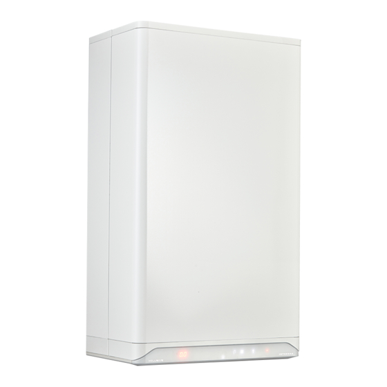
GENERAL BOILER INFORMATION General The Intergas Xclusive wall-mounted gas boiler is a room sealed unit. The boiler is intended solely to provide heat for the water in a central heating system and domestic hot water installation and is for domestic use only. -
Page 9: Operation
Operation The Intergas Xclusive is a modulating high efficiency boiler. This means that the output is adjusted according to the desired heating capacity. Two separate copper circuits are infused within the aluminium Bithermic heat exchanger. The boiler has a printed circuit board with microprocessor control, this... -
Page 10: Control Panel
Control panel The boiler has a fully integrated touch screen control panel that also displays information about the operational status, temperature settings, demand symbols and fault codes. The display has multiple functions and options please refer to section §9 for further detail. COMMENT ►... -
Page 11: Main Components
MAIN COMPONENTS Air supply duct (for 80mm twin flue only) Flue appliance adapter Ignition module Air supply duct Ignition electrode (for 80mm twin flue only) vNTC Flue gas sensor (S5) NTC Heat exchanger sensor (S0) Fan assembly Heat exchanger Expansion vessel shown as silhouette 24V DC Gas valve 3bar Pressure relief valve... -
Page 12: Standard Scope Of Delivery
Also check for any damages to the boiler or accessories and, if present, immediately notify the supplier. Boiler Wall bracket & fixings Flexible condensate hose Garantiebewijs Intergas HR-ketel Garantiebewijs Intergas HR-ketel Garantiebewijs Intergas HR-ketel Postzegel niet nodig Type/Serienr. -
Page 13: Accessories
Accessories Original Intergas accessories can be ordered separately at your local stockist. Instructions about the correct way to assemble and use these accessories are provided with the product ordered and are therefore not included within this installation manual. Item no 090347... -
Page 14: Installer Important Points
Gas Safe, and Building Control (Gas Safe Notification). ► You must register the boiler with Intergas heating ltd within 30 days of the installation to validate any warranty supplied with the boiler, via post, website or MiReg if you are the installer. -
Page 15: Installation
Condense Ødn25 syphon outlet Flue / Chimney Ø60/100 appliance (concentric, wall connection terminal ) Overall dimensions Xclusive 24 618 mm =320= Xclusive 30 618 mm 678 mm Xclusive 36 766 mm Xclusive 24 766 mm Xclusive 30 826 mm Xclusive 36 6.1.1... -
Page 16: Installation Location
Make sure the boiler is easily accessible by ensuring that the adjacent clearances are adhered to. Further dimensions *D = 600 mm Xclusive 24,30,36 * 5mm clearance from a closing door 600mm for servicing clearnances 766 mm Xclusive 24 766 mm... -
Page 17: Removing/Installing The Front Panel
6.2.2 Removing/installing the front panel ► The front cover of the boiler must be removed to perform various maintenance activities however you must be a competent Gas Safe registered engineer before carrying out the following procedure! ► Loosen both screws (1) under the boiler by using a 5 mm allen key. -
Page 18: Installing The Boiler
COMMENT ► The Intergas Xclusive has a boiler- specific siphon cup. Ensure that the correct version is ordered upon replacement. (Item no 510054) 1. Mount the wall bracket (ensure its level) 2. -
Page 19: Connection
8 radiators installed. For larger volume systems, Intergas system filter. an additional expansion vessel must be fitted. Refer to the below table or contact Intergas for further advice in these cases. SAFETY VALVE SETTING (bar) VESSEL CHARGE 0.75... -
Page 20: Thermostatic Radiator Valves
7.1.2 Thermostatic radiator valves If the radiators have thermostatic radiator valves or valves that can be closed to isolate the flow completely from the return, a minimum amount of water circulation (6ltrs/min *) must be maintained by installing a manual fixed bypass as this will not interfere with the pump modulation, (* also see §9.5). - Page 21 Underfloor option wiring diagram 230Vac 3amp NEUTRAL Switched Zone Valve EARTH Fused Spur Heating GREY (P/LIVE) V4043H (normally closed) Room thermostat Parameter P081 must adjusted to Wiring centre value '1' Time control to Heating circuit HTG on Switched Live from underfloor heating Zone Valve controls to X3 Pin 2...
-
Page 22: X-Plan Zone Hydraulic Diagram
7.1.4 X-Plan zone Hydraulic diagram Key to Hydraulic & Wiring diagrams A. Honeywell V4043H DHW Zone valve (Normally closed) B. Honeywell V4043B Heating Zone valve (Normally open) C. OpenTherm room thermostat (or programmable OT type if not using the boiler intergral timer option for the heating D. -
Page 23: X-Plan Wiring Diagram (Unvented Cylinder Option)
7.1.5 X-Plan wiring diagram (Unvented cylinder option) Comments ► The unvented cylinder must comply with G3 regulations regarding the safety controls which are normally supplied as a kit with the vessel. ► The over heat protection (with manual reset) is wired through our OpenTherm circuit to prevent the boiler from creating a hot water demand should this safety control operate. -
Page 24: S-Plan Zone Hydraulic Diagram
7.1.6 S-Plan zone hydraulic diagram Key to Hydraulic & Wiring diagrams A. Honeywell V4043H DHW Zone valve (Normally closed) B. Honeywell V4043H Heating Zone valve (Normally closed) C. Twin channel Programmer D. Cylinder overheat thermostat (manual reset) E. Pressure relief valve (3 Bar) F. -
Page 25: S-Plan Wiring Diagram
7.1.7 S-Plan wiring diagram 230Vac 3amp NEUTRAL Switched EARTH Zone Valve Fused Spur D H W M/V/S/L V4043H Room Cylinder (normally closed) thermostat thermostat LIVE SUPPLY Wiring Centre Twin channel Programmer HTG on DHW on Zone Valve C/HEATING EARTH V4043H NEUTRAL (normally closed) (24V=) -
Page 26: S-Plan Wiring Diagram (With Outside Weather Compensation Kit)
7.1.8 S-Plan wiring diagram (With outside weather compensation kit) 230Vac 3amp NEUTRAL Switched EARTH Zone Valve Fused Spur D H W M/V S/L V4043H Room Cylinder thermostat thermostat LIVE SUPPLY Wiring Centre Twin channel Programmer Relay Coil N/C COM HTG on Zone Valve DHW on C/HEATING... -
Page 27: Y-Plan Zone Hydraulic Diagram
7.1.9 Y-Plan zone hydraulic diagram Key to Hydraulic & Wiring diagrams A. Room thermostat B. Twin channel programmer C. Cylinder thermostat D. Boiler pressure reflief valve (3 Bar) E. Hot water draw off (Gravity) F. Mid position zone valve G. Cold feed and expansion tank H. -
Page 28: 7.1.10 Y-Plan Wiring Diagram
7.1.10 Y-Plan wiring diagram NEUTRAL EARTH Mid position Zone Valve M/V S/L V4073A Cylinder 230Vac 3amp Room thermostat Switched thermostat Fused Spur Wiring Centre Twin channel Programmer HTG on DHW on DHW off (24V=) (24V =) (24V =) (24V =) (24V =) (230V ~) (230V ~) -
Page 29: Connection Of Domestic Hot Water
3 metres (for expansion purposes). ► In hard water areas of 200ppm or above a scale reducer must be installed on the mains cold water inlet, Intergas recommend the Hydroflow HS38 powered via X4 connections 1 & 2. -
Page 30: Boiler With Heat Pump Boiler
As soon as the outlet temperature of the heat pump unit becomes lower than the set temperature of the mixing valve, the flow through the Intergas Xclusive will increase. If the flow becomes sufficient > 2.5lts/min then the Intergas Xclusive boiler will start producing domestic hot water. -
Page 31: Boiler With Pre-Heated Solar Boiler)
3 meters (for expension purposes). Maximum flow volume: If the domestic hot water flow is greater than 20 litres per minute, the Intergas Xclusive will start a domestic hot water demand, regardless of the outlet temperature of the heat pump unit. -
Page 32: Electrical Connection
► Should the mains power cord be replaced, this must be ordered directly from Intergas. To gain access to the electrical connections or PCB: ► Remove the front panel (see §6.2.2) and pull the PCB housing forward; then tilt it downwards. -
Page 33: Connecting Room Thermostat
Connecting Modulating OpenTherm thermostat The boiler is supplied with an OpenTherm connection X13 1/2 . This allows the connection of the Intergas Comfort Touch as well as other modulating OpenTherm thermostats without any additional modifications. The Xclusive is also suitable for OpenTherm Smart Power. -
Page 34: Connecting Outdoor Sensor
7.5.4 Connecting outdoor sensor The boiler has the facility to operate with an Intergas outdoor weather sensor, part number 203207. The outdoor sensor must be used in combination with an on/off or OpenTherm room thermostat. Outdoor weather sensor part number. 203207 In principle, any on/off or OpenTherm room thermostat can be combined with an Intergas outdoor weather sensor. -
Page 35: Connecting Boiler Sensor/Thermostat
This set consists of a Intergas gateway and a connection set. The Intergas gateway provides a connection between an Internet router and the boiler, so that the boiler can be monitored and managed via a web server using the Comfort Touch service app. -
Page 36: Flue And Air Supply Duct
► Do not mix any components, materials or ways of connecting from different manufacturers as they must be approved by Intergas Heating Ltd. 7.6.1 Flue, materials and compounds Flue materials Execution Diameter... -
Page 37: Pipeline Lengths
R/D = 1 R/D = 1 7.7.1 Replacement lengths R/D=0.5 Elbow of 90° R/D=0.5 Elbow of 45° Boiler Length Intergas Xclusive 24 100 m Intergas Xclusive 30 85 m Intergas Xclusive 36 80 m 7.7.2 Example calculation Piping Pipeline length... -
Page 38: General Layout Of The Flue
General layout of the flue The following drawing shows possible situations schematically. COMMENT ► The following schematic drawings serve as examples and the details may differ from the actual situation. Note for flue systems Cat. Note according to CE Materials The terminal is located in the façade;... -
Page 39: Horizontal Wall Terminal 60/100Mm C13
The individual flue pipe (Ø80) and/ or the internal pipe of the combi-pipe wall terminal / extension pipe must be approved by Intergas heating ltd. Allowed pipeline length ► Twin-pipe Air supply duct and flue pipe together, excluding the length of the combi-pipe wall terminal. -
Page 40: Flue Terminal Positions 60/100Mm C13
900 degree bend, which is supplied in the flue kit. Note Only use a pproved Intergas flue products with this boiler, which can be sourced from your boiler or Intergas stockist, with C33 type applications a vertical flue adapter will be required to connect to the boiler. -
Page 41: Pmk Terminal Positions 60Mm
CAUTION To reduce the telescopic flue length further: Once the flue has been installed and the appliance commissioned, the installer should observe the Separate the telescopic flue, with the terminal end, plume direction. Particular attention should be mark the length required (min. 130mm) for the term drawn to plume vapour re-entering the boiler via inal and cut square, taking care not to damage the the air intake. -
Page 42: Vertical Roof Terminal For Twin-Pipe 80Mm Flue System C33
All the flue pipe components and any terminal used must must be approved by Pitched roof Intergas heating ltd. ► Intergas Twin-pipe vertical terminal (086883) Allowed pipeline length ► Twin-pipe Air supply duct and flue pipe combined, excluding the length of the Twin-pipe wall terminal or the twin-pipe wall terminal. -
Page 43: Vertical Roof Terminal And Air Supply Duct From The Facade C53
► Shorten the air supply duct pipe to the desired length out of the wall so the cover plate can sit flush. ► Attach the Intergas air intake terminal to the wall using the 4 x screws and plugs provided ►... -
Page 44: Clamping The Flue System (Twin And Concentric)
► The flue system should have a continuous fall back to the boiler (1.5° to 3°). ► Only use Intergas approved brackets. ► Every bend or change of direction must be secured by using the approved bracket (excluding the appliance bend). - Page 45 COMMENT ► These examples are typical for both twin and concentric flue bracket positioning. Second element after first elbow Second element after first elbow...
-
Page 46: Twin Flue Terminal Positions
7.8.7 Twin flue terminal positions Terminal positions Flue Min. Air Min. Terminal Position Distance Distance Directly below to an openable window or other opening 300mm 50mm e.g. air brick Directly above an opening 300mm 50mm Horizontally to an opening 300mm 50mm 75mm 75mm... -
Page 47: Operation
Intergas recommend products manufactured from : • Fernox Tel 0330 100 7750 • ADEY Innovations Tel 01242 546 777... -
Page 48: Domestic Hot Water Facility
► Connect all the pipework then fill the heating system with mains water via the filling loop provided to a maximum pressure of 1.5 bar (The pressure can be viewed with the power supply on and the boiler switched off, by touching and holding the power LED for 2 seconds). -
Page 49: Commissioning Procedure
BS7593:2019 as per our "Terms & conditions" failure to comply will invalidate the warranty supplied with this product, a system filter should be installed on the return pipework. Garantiebewijs Intergas HR-ketel Type/Serienr. Datum installatie: Voor de ‘Garantiebepalingen Volgens geldende voorschriften Intergas HR-ketels’... -
Page 50: Clock Function
Clock function The boiler is equipped with a digital clock and offers the possibility to program both CH and DHW operations separately. To activate the clock program the following parameters have to be set: For CH operation parameter P040 = 1 (This is factory set to 1 "active") For DHW operation parameter P087 = 1 (This is factory set to 0 "Inactive") ►... -
Page 51: Shutting Down The Boiler
Shutting down the boiler CAREFUL ► Only drain the boiler and the system if the mains voltage has been interrupted and there is a chance of freezing. ► Switch the power off to the boiler. ► Remove the 3 amp fuse from the wall spur. ►... -
Page 52: Settings And Adjustments
SETTINGS AND ADJUSTMENTS The operation of the boiler can be influenced by the various (parameter) settings within the PCB. Access of these menus, can be made and modified via the touch screen display. NOTE. Some of the settings are only accessible after entering the installer’s code (see §9.1.5 and §9.3). -
Page 53: Domestic Hot Water Menu
9.1.2 Domestic hot water menu The domestic hot water menu has 2 settings and is accessible by gently tapping on the Domestic Hot Water symbol from the main menu. Within the domestic hot water menu: ► The domestic hot water temperature can be adjusted ►... -
Page 54: Central Heating Menu
9.1.3 Central heating menu The central heating menu has 3 settings and is accessible by gently tapping on the Central Heating symbol from the main menu. Within the central heating menu: ► the maximum temperature of the central heating water can be adjusted ►... - Page 55 To adjust an RF room thermostat: 1. Touch the Central Heating symbol and hold for 2 seconds. Central heating 2. The method of assignment is dependent on the type of menu 2sec room thermostat and is described within the installation manual and operation instructions of the wireless room thermostat.
-
Page 56: Service Menu
9.1.5 Service menu The service menu is accessible by first touching the display just above the power symbol then press and hold the service symbol for 2 seconds. Within the service menu: Main menu ► the test programs can be activated 2sec ►... - Page 57 (Installer’s) parameters The (installer’s) parameters within the PCB are factory set as detailed within table in §9.3. These parameters can only be modified using the installer’s access code. The installer’s code is shown on the left display and is preceded by the letter The parameters are also shown on the left display and are preceded by the letter...
-
Page 58: Info Menu
9.1.6 Info menu The info menu is accessible by touching the Service symbol from the service menu and holding it for 2 seconds. (Note if you are not in the service menu you will need to touch Info menu Ionisation current the service symbol and hold it for 2 x 2 seconds). -
Page 59: Setting And Adjusting The Clock Functions
Setting and adjusting the clock functions Show actual time ► With the boiler in standby or operating, gently tap just above the power LED to access the main menu (also see §9.1.1). The actual time is shown in the left display. The symbols Clock shown (boiler standby) will also illuminate. -
Page 60: Programming The Dhw Pre-Heat On / Off Times
To apply the clock program ► With the boiler in standby or operating gently tap just above the power LED to access the main menu (also see §9.1.1). ► Tap on the Central Heating symbol. The current temperature of the central heating water is illuminated in the left display. - Page 61 To operate the preheat with the programmed times ► With the boiler in standby or operating gently tap just above the power LED to access the main menu (also see §9.1.1). ► Tap on the domestic hot water symbol . The current temperature is illuminated in the left display.
-
Page 62: Parameters
2 = Xclusive Instantaneous water heater 3 = Xclusive System boiler 75 = Xclusive 36 Set maximum central heating output ------- 100 = Xclusive 24 / Xclusive 30 P010 P010 25% to 100% (see §9.5) 0 = overrun active Central heating pump setting... -
Page 63: Switching Dhw Comfort Function On And Off
(Δt) between the flow and return is correct for the system design criteria. If the central heating load modulates between the minimum and maximum value, the pump capacity will modulate proportionately with it. Pressure loss graph boiler central heating side A. Xclusive 24 B. Xclusive 30 C. Xclusive 36... -
Page 64: Outside Weather Compensation
Outside weather compensation When an optional Intergas outdoor sensor is connected, the heating flow temperature will be automatically controlled according to the set heating curve, depending on the outside temperature at that time. The weather-dependent control functions solely with an on/off room thermostat. -
Page 65: Conversion To Another Gas Type
Conversion to another gas type IMPORTANT ► Only qualified competent gas safe registered engineers may work on the boiler and Intergas training is recommended before undertaking the following procedure. If the boiler is connected to a different gas type than originally set by the manufacturer, then the gas restriction ring must be replaced. -
Page 66: Gas/Air Control
Gas/air control IMPORTANT ► Only qualified competent gas safe registered engineers may perform adjustments to the gas/ air ratio control on the gas valve. The gas/air control valve is factory set to optimise combustion for the gas type used. The gas type (Natural Gas or LPG) is detailed on the data plate situated under the boiler The boiler must only be operated with the gas category specified on the aforementioned data plate. -
Page 67: Inspection Of The Gas Air Control Valve
9.10 Inspection of the gas air control valve 9.10.1 Measuring the flue gas at maximum output A. Switch off the boiler (see §8.2.1). – – A dash will appear on the right display and the central heating pressure will be visible on the left display. B. -
Page 68: 9.10.2 Measuring The Flue Gas At Minimum Output
Table 2: Allowed CO (H) limits at maximum output (open casing) Gas category Value limits Natural gas Upper limit 10.8 Lower limit IMPORTANT ► Any readings that are out of tolerance during maximum output cannot be corrected by adjusting the gas valve. The boiler must be meticulously inspected for gas quality / type, correct components used (especially the gas... - Page 69 IMPORTANT ► The gas air control is correctly set if the measured value at minimum output falls within the indicated upper and lower limits. Adjustment of the gas air control is not necessary in this case. The setting at minimum output must be adjusted using the method described in §9.10.3 if the measured value is outside the indicated limits.
-
Page 70: 9.10.3 Minimum Output Correction
9.10.3 Minimum output correction Before the minimum output correction is performed, the maximum output and minimum output measurements must be completed. The measured CO (H) value at maximum output is important for determining the correct value for the setting at minimum output (see §9.10.1 and §9.10.2). -
Page 71: Faults
Fault code illuminated Resetting the boiler The boiler can be reset by touching the flashing Service button and holding it for 2 seconds. If the fault code reoccurs an Intergas trained engineer should be requested. Reset 2sec IMPORTANT ► Using the fault code table below to establish the cause of the issue before attempting to reset the boiler. - Page 72 ► Check for the correct operation of central heating flow sensor S1. ► Replace central heating flow sensor S1. IMPORTANT ► Any replacement components must be original Intergas parts. ► Using 3rd party components or installing them incorrectly can lead to serious consequences, with a risk to health,...
-
Page 73: Other Faults
10.2 Other faults 10.2.1 No heat (central heating) Possible causes Analysis Solution The power LED is not illuminated. → → Check the power supply. Check the fuse; see Electrical schematic §12.1. ↓ → Switch on the boiler by touching just above the power LED and →... -
Page 74: No Domestic Hot Water (Dhw)
10.2.4 No domestic hot water (DHW) Possible causes Analysis Solution The power LED is not illuminated. → → Check the power supply. Check the fuse; see Electrical schematic §12.1. ↓ Flow turbine does not work. → → Replace the flow turbine. ↓... -
Page 75: 10.2.7 Burner Resonates
In addition to error codes, the burner control can also show notifications on the display. Notifications are displayed if an anomaly occurs somewhere in the system that does not affect the vital functioning of the system. Notifications disappear if the system can fix the abnormality. Intergas Heating should be consulted if a notification returns repeatedly. -
Page 76: Maintenance
MAINTENANCE The boiler and the system must be inspected annually by an qualified competent gas safe registered engineer. The boilers heat exchanger should be cleaned and inspected as stated below at each service interval. CAREFUL ► After completion of the Annual service procedure all 26 (9) safety checks must be performed and the results recorded within the service &... - Page 77 ► Return the plastic ball to the syphon base and attach the circlip. ► Check that the ball and circlip have been installed correctly ca. 6 cm (6). Make sure that the top of the circlip is about 6 cm below the edge of the syphon base.
-
Page 78: Annual Service Continued (Internal Maintenance)
11.3.1 Annual service continued (cleaning) ► Clean the slats of the heat exchanger from top to bottom with a brush or Intergas comb (use a vacuum cleaner to remove debris). ► Clean the underside of the heat exchanger. ► Only clean the underside of the front panel. -
Page 79: Annual Service (Re-Assemble)
11.4 Annual service (re-assemble) IMPORTANT ► Replace the front plate O-ring at least every 3 years or if damaged/ discoloured. Art.no: 877927 — Xtreme 24/30 620274 — Xtreme 36 ► Check and replace any other worn gaskets. Also check they are correctly located. ►... -
Page 80: Annual Service Checklist
11.5 Annual service checklist Inspection at Maintenance Activity every annual must be carried service out at regularly Isolate the boiler from the fused spur and make safe (ref TB118) check the correct 3amp fuse has been fitted. Carry out inspection of boiler for dust and dirt and clean where necessary. -
Page 81: Technical Specifications
TECHNICAL SPECIFICATIONS Boiler category C13; C33; C53 Gas inlet pressure G20: 20 mbar, G31: 37 mbar Suitable for gas 2H3P Technical data Xclusive Domestic hot water Nom. input rating (lower value) 3.6 – 25.1 3.6 – 30.5 3.6 – 32.7 Tap threshold l/min ∆T 25°C... -
Page 82: Electrical Schematic
12.1 Electrical schematic... - Page 83 230V~ component Connector Connections Designation Description 1 – 2 – 3 – 4 – 5 – 6 1 – 2 – 3 Central heating pump 1 – 2 On/off room thermostat 230V Shut-off valve underfloor heating or variable output control 1 –...
-
Page 84: Product Fiche According To Celex-32013R0811
12.2 Product Fiche according to CELEX-32013R0811, Appendix IV Intergas Heating Ltd Unit 2 Easter Park Supplier Worcester Road Kidderminster DY11 7AR Intergas Xclusive Type designation Symbol Unit Seasonal energy efficiency class for room heating Nominal heat output (capacity) rated Seasonal energy efficiency class for ŋ... -
Page 85: Spares Short List
SPARES SHORT LIST Description Part number PCB complete with housing 074104 230V EBM NRG130 Fan assembly (complete with 877807 seal & 2 x 312027 M5 nuts) 074304 S0 NTC Temperature sensor (heat exchanger) 230034 S1 NTC Temperature sensor (CH Flow) Clip on 18mm 230054 Modulating Yonos Wilo CH pump 074604... - Page 86 The boiler and Intergas system filter* must both be registered The central heating system must be maintained in accordance for warranty with Intergas by either the installer or you the with the Benchmark Guidance on water Treatment in Central householder, within 30 days of the boiler being installed.
-
Page 87: Benchmark Commissioning & Warranty Validation Service Record
BENCHMARK COMMISSIONING & WARRANTY VALIDATION SERVICE RECORD Benchmark Commissioning & Warranty Validation Service Record It is a requirement that the boiler is installed and commissioned to the manufacturers’ To instigate the boiler warranty the boiler needs to be registered with the manufacturer within one month of the installation. - Page 88 GAS BOILER SYSTEM COMMISSIONING CHECKLIST & WARRANTY VALIDATION RECORD Address: Boiler make and model: Boiler serial number: Commissioned by (PRINT NAME): Gas Safe registration number: Company name: Telephone number: Company email: Company address: Commissioning date: Heating and hot water system complies with the appropriate Building Regulations? Time, temperature control and boiler interlock provided for central heating and hot water Boiler Plus requirements (tick the appropriate box(s)) Weather compensation...
- Page 89 SERVICE & INTERIM BOILER WORK RECORD It is recommended that your boiler and heating system are regularly serviced and maintained, in line with manufacturers’ instructions, and that the appropriate service / interim work record is completed. Service provider When completing a service record (as below), please ensure you have carried out the service as described in the manufacturers’ instructions. Always use the SERVICE/INTERIM WORK ON BOILER SERVICE/INTERIM WORK ON BOILER Date:...
- Page 90 SERVICE & INTERIM BOILER WORK RECORD It is recommended that your boiler and heating system are regularly serviced and maintained, in line with manufacturers’ instructions, and that the appropriate service / interim work record is completed. Service provider When completing a service record (as below), please ensure you have carried out the service as described in the manufacturers’ instructions. Always use the SERVICE/INTERIM WORK ON BOILER SERVICE/INTERIM WORK ON BOILER Date:...
- Page 92 All rights reserved. The information provided applies to the standard version of the product. Intergas Heating Ltd can therefore not be held liable for any damage ensuing from specifications that deviate from the standard version of the product. Although the available information has been composed with all possible care, Intergas Heating Ltd cannot be held liable for any errors in the information or for the consequences of such.
Need help?
Do you have a question about the Xclusive 24 and is the answer not in the manual?
Questions and answers