
Related Manuals for HYDAC ELECTRONIC HMG 3010


Summary of Contents for HYDAC ELECTRONIC HMG 3010
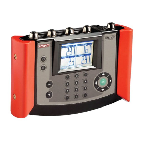
- Page 1 Portable Data Recorder HMG 3010 User Manual (Translation of original instructions) Edition 2013-03-26 - V04 R01 Part No.: 669855...
- Page 2 HMG 3010 Page 2 Edition 2013-03-26 - V04 R01 Part No.: 669855...
-
Page 3: Table Of Contents
HMG 3010 Page 3 Table of contents Tasks and Functions of the HMG 3010 ............4 1.1 Standard functions of the HMG 3010 ............. 4 1.2 CAN functions of the HMG 3010 ..............6 About Your HMG 3010 .................. 7 2.1 Items supplied .................... -
Page 4: Tasks And Functions Of The Hmg 3010
Applications are primarily in mainte- nance and servicing, troubleshooting and test rigs. The HMG 3010 can monitor signals from up to ten sensors simultaneously. The unit has 5 input jacks for connecting the sensors; if necessary this number can be doubled using a Y adapter (if more than 5 sensors are required). - Page 5 0.1 ms. This function of course requires suitable fast sensors to be used. The most attractive feature of the HMG 3010 is its ability to record the dynamic processes of a machine in the form of a measurement curve and render them as a graph — and, moreo- ver, online and in real time.
-
Page 6: Can Functions Of The Hmg 3010
HMG 3010 Page 6 The HMG 3010 communicates with a computer via a USB or serial port. HYDAC soft- ware HMGWIN which is specific to the HMG 3010, is supplied for convenient post- processing, rendering and evaluation of measurements on your computer. It also ena- bles the HMG 3010 to be operated directly from your computer. -
Page 7: About Your Hmg 3010
Compliance with European Standards The HMG 3010 series portable data recorders have the CE mark and thus comply with all current German regulatory requirements and European standards relating to the operation of these units. This ensures compliance with the applicable directives relating to electromagnet- ic compatibility and the safety provisions according to the low-voltage directive. -
Page 8: Safety Information
Page 8 3.1 Safety information The HMG 3010 series Portable Data Recorder can be operated safely provided it is used in accordance with its proper, designated use. However, in order to avoid any risk to the operator or any damage due to incorrect handling of the unit, please adhere strictly to the following safety instructions: •... -
Page 9: Commissioning
HMG 3010 Seite 9 4 Commissioning 4.1 Operating Elements On/Off button Brightness setting of the display ESC key To cancel an entry or go Back step by step Shift key (↑) Switches number-pad textpad when pressed; the textpad is active only as long as the Shift key is pressed. -
Page 10: Connections
HMG 3010 Seite 10 4.2 Connections DC IN RS232 Y adapter 4 sensor input sockets* each with two measurement channels (channel A – D or A - E E – H) to connect up to 8 analogue sensors or up to 4 SMART sensors, e.g. for... -
Page 11: Switching On The Instrument
HMG 3010 Page 11 4.3 Switching on the instrument When starting the unit up for the first time the Welcome start-up screen appears. Select your language using the 5-way navigation key (select or checkmark your option by pressing OK) and set the date and time. Select the desired format, and then enter the current date and time via the keypad. - Page 12 • Altering the sensor settings • While recording an event log • About HMG 3010 When finishing recording • Before resetting the Min/Max values it is fre- quently necessary to determine when the Min/Max values were last reset. To do this, go to Extras in the function bar and then About HMG 3010.
-
Page 13: Getting Started Guide
(HSI sensors). For a detailed description of all the settings, see Detailed Operating Instructions. The examples are based on the factory settings of the HMG 3010. Simply follow the steps described here. If you don’t know the status of your HMG 3010 because there might be more than one user in your company using the HMG, you can simply restore the unit to its "as supplied"... - Page 14 HMG 3010 Page 14 When HSI sensors with automatic sensor detection are used, the HMG automatically detects the measurement range and the unit of measurement of the two connected pres- sure transmitters and shows them in the dis- play with the actual measured values. You can also display the minimum and maximum values for the sensors.
- Page 15 HMG 3010 Page 15 The HMG now shows the measured values in the 7-segment display panes. Depending on the setting, the Min/Max values are shown in addition to the current measured values. The Recording menu is used for recording measurement curves. During recording, the...
- Page 16 HMG 3010 Page 16 In the Recording option line, select End when time has elapsed in the same man- ner. In the Automatic operation line, select the Deactivated option and in the Magnified section the 5 second option. Your display now shows the settings you made for recording measured values (see screenshot).
- Page 17 HMG 3010 Page 17 Graphic rendering provides a faster visual impression of the changes in the measured values. To have the measurement curve displayed while recording, select Graph + OK. The screenshot on the right shows you the curve plotted for our example.
-
Page 18: Detailed Operating Instructions
"System pressure". For connection to CAN-bus: If the connection adapter ZBE 3010 is plugged into D/H, the HMG 3010 automati- cally switches channel D to CAN-bus and channel H to off. For all the setting options for CAN-Bus, see Section 6.5‚... - Page 19 HMG 3010 Page 19 The various options available for channels A to H are demonstrated here using channel A as an example. Select the measurement range entry on the right of the channel us- ing the navigation keys and press OK. This takes you to the menu window for the se- lected channel.
- Page 20 Pressure difference dP and Orifice measurement Q=f(dP). With Pressure difference dP the HMG 3010 gives you the opportunity to dis- play the difference in pressure between channel A – channel B with a very high de- gree of accuracy.
- Page 21 HMG 3010 Page 21 function Orifice measurement Q=f(dP) enables you to carry out a flow rate measurement by measuring the differ- ential pressure at a flow rate measurement orifice (e.g. HYDAC EVS 1000). For both these modes HYDAC HSI pres-...
- Page 22 If a curve for a pressure transmitter combination already exists, you can quit the menu again by selecting Back or the Esc key. The HMG 3010 automatically selects the appropriate curve. If you quit the menu and the HMG 3010 detects that no curve exists for this combination, you will get the message shown on the right.
- Page 23 HMG 3010 Page 23 When doing this, identify which pressure transmitter has been connected to channel A and which to channel B, since the pressure transmitters must be re-connected in the same way later when taking measurements. Connect pressure transmitter hydraulically so that the two instruments are subjected to the same pressure.
- Page 24 HMG 3010 Page 24 In order to measure the flow rate using a differential pressure measurement at a flow rate orifice, select the item Orifice meas- urement Q=f(dP). Then select the number of decimal places and the unit (of measure- ment).
- Page 25 HMG 3010 Page 25 Input channels I and J are for digital (not analogue) signals. As the input signal you can choose between Count pulses and Frequency signal. There are many possibil- ities for this, e.g. speed sensors, proximity switches, pulse generators, flow rate meas- uring instruments with a frequency signal, HYDAC HDS 1000, to name only a few.
- Page 26 Examples of count pulses: 1) The switching output of a proximity switch on a conveyor belt is connected to the fre- quency input of the HMG 3010. Enter "1" as the Factor and the expected maximum quantity to be counted (maximum 30000) as the Upper measurem.
- Page 27 These two channels can be used to display a differential between 2 input channels, or to calculate a power. When setting to Differential the HMG 3010 calculates for channel K the difference be- tween channel A/channel B and for channel L the difference between channel C/channel D.
- Page 28 HMG 3010 Page 28 You should set this value as close as possi- ble to that of the expected power value in order to get the best possible graphical dis- play. If there are measured values which are higher than the upper measurement range, these are not lost.
-
Page 29: Changing Display Settings
HMG 3010 Page 29 6.1.2 Changing Display Settings The next submenu of the Change Display Settings item enables you to make settings affecting the display and rendering of meas- ured values and the display size in keeping with your measurement task. Select the item using the arrow keys, followed by OK. - Page 30 HMG 3010 Page 30 The screenshots on the right show the measured values of four sensors when the 2 display panels option is selected and the Min/Max display is activated. Consequently, the display only shows the measured values of two sensors at a time. Use the arrow keys (▲) and (▼) to see the measured values of...
-
Page 31: Zeroing Measurement Channels
HMG 3010 Page 31 6.1.3 Zeroing Measurement Channels You can re-zero the measurement channels in the Settings menu. This function is used to mask out backpressure buildups present in the system. For example, if a pressure of 3 bar is present at a pressure transmitter... - Page 32 HMG 3010 Page 32 Switching the HMG unit or measurement channels OFF/ON doesn't automatically de- lete the newly set zero point. The following message is shown when switching the HMG off and then back on: "Some channels have a zero offset."...
-
Page 33: Changing The Initial Setup
HMG 3010 Page 33 6.1.4 Changing the Initial Setup Change initial setup is a submenu of the Settings menu. To make changes to the initial setup, press OK. You can now change the following items: Language You can choose between German, English and French. - Page 34 HMG 3010 Page 34 Note! Automatic conversion of measured values to the selected unit of measurement will not work unless Automatic detection (HSI) mode is selected under Settings – Meas- urement Channel Settings. Select the unit of measurement to be changed, followed by OK.
- Page 35 Page 35 PC Connection The HMGWIN 3000 and CMWIN software enables you to make online measurements and settings in the HMG 3010, in addition to further processing, archiving, documenting and updating etc. Data transfer generally takes place via the USB port.
-
Page 36: Administer Settings (Save, Load
HMG 3010 Page 36 6.1.5 Administer settings (save, load, ...) All of the measurement channel settings made by you in the HMG for the last meas- urement can be saved and then reloaded later in order to be able to repeat the same measurement periodically, for example. - Page 37 HMG 3010 Page 37 In the submenus Load stored settings or Delete stored settings, you are shown a list of all the saved settings from which you can Load or Delete individual settings. Navigate to a setting using the arrow keys and highlight using OK.
-
Page 38: Recording Menu
HMG 3010 Page 38 6.2 Recording Menu Here the HMG enables you to perform a measurement for a specific period of time and save it. This recording can be rendered as a graph or a table. To do this, proceed as... - Page 39 HMG 3010 Page 39 Sampling rate This item enables you to set the rate at which the HMG reads a measured value from the sensors and saves it in the internal memory. A measurement curve may com- prise up to 500,000 measured values. Se-...
- Page 40 HMG 3010 Page 40 The sampling rate which can be set is also dependent on the active measurement channels: 0.1 ms max. 2 analogue input channels • 0.2 ms max. 4 analogue input channels • 0.5 ms all 10 input channels •...
- Page 41 HMG 3010 Page 41 Automatic mode In this menu point, you define whether the recording (using the settings previously set) is to be started just once or at regular inter- vals. Deactivated means that the recording is started as predefined, and is ended once the stop condition occurs and is saved.
- Page 42 HMG 3010 Page 42 Example of recording a Simple Measure- ment Curve The settings made for the example shown on the right mean that the measured values of channels A and B are recorded with a sampling rate of 1 ms (i.e. 1000 measured...
- Page 43 HMG 3010 Page 43 Before doing this, you can have the meas- urement shown again as a curve (Graph + OK) or as a measured value table (Table + OK). When doing this, other tools are offered for analyzing the chart or table. For more infor-...
- Page 44 HMG 3010 Page 44 Measurement Curve with Trigger Measurement curve with trigger is another recording option. Trigger means that a measurement curve can be started automat- ically when one or more specific events oc- cur. Examples of events are when a limit is...
- Page 45 HMG 3010 Page 45 Event: Actuation of button/key This setting is designed to trigger a meas- urement when a button is specifically ac- tuated. After starting the recording, you can trigger measurement by selecting Trigger in the function bar (+ OK).
- Page 46 HMG 3010 Page 46 Event: Leaving measurement window This trigger event is very similar to Specific value. You can specify a Lower Limit and an Upper Limit. The trigger is activated when the measured value enters the meas- urement window. However, recording is not...
- Page 47 HMG 3010 Page 47 Linking Events You also have the option of linking events. Without linking, each of the four events acts alone and independently as a trigger for a measurement recording. In the line Joint events (options shown to the right) a drop-down list opens containing the linked event options.
- Page 48 HMG 3010 Page 48 The next setting parameter for recording a triggered measurement curve is Pre/post trigger. After starting a triggered measure- ment curve the HMG begins to record the measured values for the recording time set (e.g. 30 seconds). If the trigger event does...
- Page 49 HMG 3010 Page 49 Example of an Automatically Triggered Measurement The following occur in a hydraulic press from time to time: defective components, ruptured hoses or cracked cylinders. You suspect there may be extremely high pressure peak- ing in three hydraulic circuits and want to monitor the press for pressure surges for an extended period of time.
- Page 50 HMG 3010 Page 50 As soon as you confirm this with OK, meas- urement is activated, resulting in the screen shown on the left. Selecting Graph means a measurement curve is plotted and displayed (cf. top screenshot), selecting Measured values takes you to the normal measured values screen (cf.
- Page 51 HMG 3010 Page 51 Event Log The Event Log option enables you to store measured values as a table. A line in the table contains the current measured value, in addition to the Min and Max value of each active channel. The trigger settings enable...
- Page 52 HMG 3010 Page 52 In order to also manually generate a • measured value line, set a second event to Actuation of button/key. Automatic measurement: Deactivated • When measurement starts, a new menu window Event Log Recording — Status opens, enabling you to track the measure- ment on the basis of the settings.
- Page 53 HMG 3010 Page 53 Using the arrow keys of the 5-way navkey, you can select the arrows next to the scroll bar. After confirming with OK, you can scroll in the table up/down and left/right. After con- firming with OK, you can scroll up/down and left/right in the table.
- Page 54 HMG 3010 Page 54 The Comment item enables you to enter a text, e.g. a description indicating the opera- tional status of the unit or system while the recording was being made. The HMG saves the measurement settings together with each recording so that a detailed measure- ment log is created.
- Page 55 HMG 3010 Page 55 Start-Stop Measurement The Start-Stop Measurement option allows you to start a recording when triggered by a defined condition and to stop it again when triggered by a second defined condition. If the stop condition does not occur within...
-
Page 56: Viewing Recordings
HMG 3010 Page 56 6.2.2 Viewing Recordings The View recording item in the Recording menu will display a list of the recordings stored in the HMG. Use the arrow keys to select the measurement you wish to view. The selected recording is indicated by an arrowhead and is blue-highlighted. - Page 57 HMG 3010 Page 57 Graph A measurement can also be rendered as a measurement curve. To do this, select Graph + OK in the function bar. The screen- shot on the right shows what appears next in your display. The measurement is scaled throughout the entire time range (x-axis) and measurement range (y-axis).
- Page 58 HMG 3010 Page 58 Back: Back/Esc enables you to return to the previ- ous menu. Automatic: Automatic renders all individual curves op- timally "automatically". When selecting Au- tomatic (+ OK) the y-scaling is automatically adapted for each active channel separately, i.e.
- Page 59 HMG 3010 Page 59 Use the ► and ▲ arrow keys while holding the Shift key (↑) down to enlarge a portion of the measurement in the x- or y-axis. Conversely use the ◄ and ▼ arrow keys while holding the Shift key down to de- crease or "squash"...
- Page 60 HMG 3010 Page 60 Ruler: When the Ruler is activated, the screen appears as shown in the screenshot. The function bar contains the commands which can be accessed for the ruler. Using the arrow keys by themselves enables you to determine the pressure at a particular point in time.
- Page 61 HMG 3010 Page 61 Tracker: Using the Tracker is similar to using the ruler. The difference is that each value ac- tually measured is rendered by a point. A ruler only appears for the purpose of "track- ing" the curve in time. The tracker "jumps"...
- Page 62 HMG 3010 Page 62 Display all: Display all renders the recording throughout the entire recording period with all the measured values. This option is used, for example, to restore the original condition of a recording. Display All + OK restores the...
- Page 63 This is one of the various options of- fered by the HMG 3010 to enlarge interest- ing parts of graphs. After confirming the Lower limit line with OK, you can change the value.
- Page 64 HMG 3010 Page 64 Entering the following new settings for "Sen- sor measurement 3(1)" would result in the curve shown right: Scaling (lower and upper limit) of y-axis: 0 - 50 bar - Control line Time range of x-axis: 4.00 - 6.00 s - Time...
- Page 65 HMG 3010 Page 65 Table Tables are useful for displaying individual measured values. Select Table (+ OK) in the function bar to select a stored recording and have its values displayed. For a simple measurement curve recording you are shown a measured values table list-...
- Page 66 HMG 3010 Page 66 The date and Min/Max values can be hidden so as to make tables easier to read. You can hide or display Min/Max and the Date direct- ly in the function bar with OK. You can also hide or display individual chan-...
-
Page 67: Deleting Recording
HMG 3010 Page 67 6.2.3 Deleting Recording Any recording can be deleted when no long- er needed. To do this, select Delete record- ing in the Recording menu + OK. You are now shown a list of all the stored recordings. -
Page 68: Extras Menu
Use Reset to set the stopwatch back to zero. About HMG 3010 The About HMG 3010 menu provides an overview of available power supply, how much memory is still free, when the Min and Max values were reset last, and the address of HYDAC ELECTRONIC. - Page 69 All data stored in the HMG 3010 (measurements, settings, ...) is deleted when the update is imported. Back up this data to a PC using HMGWIN 3000 before starting the update. Con- nect the power supply to the HMG 3010 to ensure a secure voltage supply during the up- date.
-
Page 70: Smart Sensors
Regardless of the sensor used, its parameters can be set. CAUTION: To connect SMART sensors to HMG 3010 see “Connection requirements” and “Wiring diagrams” in each sensor user manual. -
Page 71: Smart Sensors Menu
6.4.2.3 Sensor Recordings In this menu you can transfer long-term recordings created by the SMART sensor to the HMG 3010, or delete them from the SMART sensor's memory. Refresh enables you to check whether new recordings are present. - Page 72 Read configuration from sensor This menu item enables you to read the configuration of the SMART sensor and transfer it to the HMG 3010. You can ac- cept the suggested name+number combi- nation, or enter a new one. Edition 2013-03-26 - V04 R01...
- Page 73 SMART sensors. Display stored sensor configuration This enables you to display a configuration which is stored in the HMG 3010. You are then shown detailed information on the sensor configuration. Delete stored sensor configuration This menu enables you to delete a sensor configuration.
-
Page 74: Can Functions
Page 74 6.5 CAN Functions The HMG 3010 can be connected to a CAN bus system in conjunction with the CAN adapter ZBE 3010. In this operating mode, the following functions are available in the HMG. Read-out of up to 32 measured values from predefined CAN messages •... -
Page 75: Main Menu Can Bus
≥ 100 mA is directly connected. - The entire voltage for the connected bus system is to be supplied via the ZBE 3010. To supply voltage to the ZBE 3010 the HMG 3010 power supply (Part No.: 6054296) can be used. Signal... - Page 76 HMG 3010 Page 76 • In the Name line, you can assign a unique alphanumeric name for the CAN-message or measured value. • In the lines Lower measurement range and Upper measurement range enter the appropriate sensor values (e.g. 0 and 600 for a 0 ..
- Page 77 HMG 3010 Page 77 • In the Data format line, enter the format of the data value to be read. The following formats are available: - 8; 16; 24; 32-Bit Integer - 8; 16; 24; 32-Bit Unsigned - 32-Bit Real •...
-
Page 78: Technical Data
HMG 3010 Page 78 6.6 Technical data Sensor inputs The HMG features: 4 sensor input jacks (channel A – H) for up to 8 analogue sensors, • or up to 4 SMART sensors and 1 input jack with 2 digital inputs (channel I - J) and •... - Page 79 HMG 3010 Page 79 Battery life (from fully charged) HMG 3010 without sensors approx. 11 hours • HMG 3010 with 2 sensors approx. 9 hours • HMG 3010 with 4 sensors approx. 7 hours • HMG 3010 with 8 sensors approx.
-
Page 80: Cleaning
HMG 3010 Page 80 7 Cleaning The HMG 3010 must not be cleaned with aggressive agents (e.g. alcohol, screen clean- er,...). For cleaning we recommend using a slightly damp cloth. 8 Accessories CAN Adapter • Part no. 921238 Part description... - Page 81 • Part no. 6042959 Part descr. Case for HMG 3010 & accessories Part no. 909795 Part descr. Bag with carrying strap for HMG 3010 Part no. 909739 Part descr. ZBE 31 (car charger for HMG 3010) Part no. 3236597 Part descr. ZBE 34 (adapter M12/Binder; 4 .. 20 mA, 2-conductor) Part no.
-
Page 82: Examples Of Connections
HMG 3010 Page 82 9 Examples of Connections Pressure transducer Temperature UVM 3000 transmitters Flow rate transmitters Charger Connection cable HMG-PC (USB) Rpm probe HDS1000 A / E B / F C / G D / H Pin 1: 12 V; 50 mA Pin 1: 12 V;... -
Page 83: Pin Assignment
HMG 3010 Page 83 9.1 Pin assignment Note on H*: Channel H can be used for sensors with an analogue signal (connection to jack D/H) or for voltage measurements of -10 V to +10 V (connection to jack T). The input signal is selected when setting the measurement range for channel H. - Page 84 HMG 3010 Page 84 Power supply connector: JEITA RC-5320 A Pin 1 (outer contact): 0V (GND) Pin 2 (inner contact): +12 .. 30 V DC USB end device connector: Standard USB end device connector for standard USB end device connector cable.
- Page 85 HMG 3010 Page 85 HYDAC ELECTRONIC GMBH Hauptstr. 27 D-66128 Saarbrücken Germany Web: www.hydac.com E-Mail: electronic@hydac.com Phone: +49-(0)6897-509-01 Fax: +49-(0)6897-509-1726 HYDAC Service If you have any questions concerning repair work, please do not hesitate to contact HYDAC Service: HYDAC SERVICE GMBH Hauptstr.
Need help?
Do you have a question about the HMG 3010 and is the answer not in the manual?
Questions and answers