Table of Contents
Advertisement
Quick Links
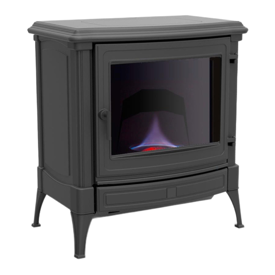
S31
Models 8800
Oil Burning Stoves
OWNER'S MANUAL
INSTALLATION
&
OPERATING
INSTRUCTIONS
Report #0261HH006S
Ce manual est disponible en Francais a
www.hearthstonetech.com
PLEASE READ THIS ENTIRE OWNER'S MANUAL BEFORE YOU INSTALL AND USE YOUR NEW S31 OIL
STOVE. To reduce the risk of fire, follow the installation instructions. Failure to follow these instructions may
result in property damage, bodily injury, or even death.
Never Burn Wood Products in this Stove! Use Heating Oil Only.
SAVE THESE INSTRUCTIONS FOR FUTURE REFERENCE!
CONTACT LOCAL AUTHORITIES HAVING JURISDICTION (BUILDING DEPARTMENT or FIRE
OFFICIALS) ABOUT PERMITS REQUIRED, RESTRICTIONS AND INSTALLATION INSPECTION IN
YOUR AREA.
Models # S31
Manual6400-41401
R: 08//27/18
Advertisement
Table of Contents

Subscribe to Our Youtube Channel
Related Manuals for HearthStone Nestor Martin S31


Summary of Contents for HearthStone Nestor Martin S31
- Page 1 Models 8800 Oil Burning Stoves OWNER'S MANUAL INSTALLATION & OPERATING INSTRUCTIONS Report #0261HH006S Ce manual est disponible en Francais a www.hearthstonetech.com PLEASE READ THIS ENTIRE OWNER’S MANUAL BEFORE YOU INSTALL AND USE YOUR NEW S31 OIL STOVE. To reduce the risk of fire, follow the installation instructions. Failure to follow these instructions may result in property damage, bodily injury, or even death.
-
Page 2: Installation
INTRODUCTION A Nestor Martin oil stove is the elegant result of many years of engineering research and design expertise. It was built by people who are proud of knowing the Nestor Martin oil stove is the finest stove produced and would like to know their efforts will bring many years of pleasure, instilling the pride of ownership it deserves. - Page 3 Dimension/Distance Inches Millimeters 24 ½” 11 ¾” 15” 6” Additional clearances for corner installations Measurement Inches Millimeters 11 ¾” 300 mm 11 ¾” 300 mm These measurements are a guideline only. In all installations, surrounding flammable materials must not exceed 176 F (80°C).
- Page 4 THE FLUE There is often confusion as to the terms “flue” and “chimney” and for the purposes of this manual we define whatever duct conveys the products of combustion as the flue, and the term chimney to mean any masonry structure within which the flue may be contained.
- Page 5 Atmospheric influences Wind blowing across the flue cap can increase the negative pressure within the flue proportionate to the wind speed. Because wind speed is never constant, the varying effect this may have on the stove would be unacceptable. To control this, the stove is fitted with a draft stabilizer. When the negative pressure from the stove.
- Page 6 FLUE PRESSURE ADJUSTMENT REQUIREMENTS The flue creates the negative air pressure within the stove which induces the air into the burner. For the correct operation of the burner this air flow must be proportioned to the firing rate of the burner. The following chart below illustrates the required negative air pressures relative to the burner settings, with the shaded band giving the tolerance within which the burner will give satisfactory performance.
-
Page 8: Flue Connection
FLUE CONNECTION IDEAL TO BE AVOIDED... - Page 9 IDEAL TO BE AVOIDED Connect only one stove per chimney...
- Page 10 FUEL LINE AND TANK INSTALLATION The Oil Storage Tank An easily read level indicator installed on the oil storage tank will help the user monitor fuel consumption and avoid running out of fuel. It is important that this level indicator is calibrated in volumetric units enabling the oil delivery driver to ensure he does not overfill your tank.
- Page 11 near the stove and above the metering valve. Finally, another manual isolation valve should be positioned as close to the stove as possible to enable all supply to be turned off for stove maintenance. It some areas, it may be possible to bury oil tanks or install them in basements. It is important to remember that any with any oil installation, the simpler the system can be desgned and the shorter the sullpy line can be kept while still meeting local codes will will ensure more problem free operations.
- Page 12 THE CARBURATOR Model Toby DVR5 Control knob Attachment screws (5 in number) Control lever Float assembly Anti-overheating Safety device Draining screw with washer Filter lid Filter washer Flat filter 10 Washer 11 Metering stem with spring and washer 12 Lid assembly 1.
-
Page 13: Stove Installation
STOVE INSTALLATION Installation of the S31 and should not be performed on high wind days, and should only per perfomed by qualified technicians having the appropriate testing equipment and working knowledge of the relevant standards and regulations. The customers who will operate the stove are an essential component of any installation. Ensuring they understand the operation of the stove, its controls and what to expect from the installation, whether simple or complex, is a significant aspect of thie installation process. -
Page 14: Lighting And Operating
- a safety float valve will isolate the fuel should the levels within the valve body become too high. The safety float will cause the arming lever to “trip” whenever the fuel levels become too high. Once “tripped “, resetting the arming lever may need to be done several times before the fuel level within the valve falls sufficiently to allow reliable operation. - Page 15 Post-Ignition Start Up (First Fire Only/Commisioning) Shortly after the stove is lit, a stove air pressure reading should be taken and the pressure monitored at fifteen minutes intervals to ensure the stove and the flue are operating safely with sufficient air. As the stove and flue warm, the supply of air being induced into the burner will increase, and it will be possible to increase the stove’s burn rate incrementally until the stove is running at maximum output.
- Page 16 Low Setting Adjustment Screw -Clockwise to decrease the flame. -Counter clockwise to increase the flame With a satisfactory minimum setting achieved, the stove should be turned to its maximum fuel rate and allowed to run for at least fifteen minutes before measuring the negative pressure and adjusting the draught stabilizer (if necessary).
-
Page 17: Maintenance
MEDIUM SETTING Flames arrive up to about ¾ of the firebox. The top of the flames is "white/yellow". The base of the flames is blue. Blue spears only on the top of the burner. Base of catalyst is red. MAXIMUM SETTING A large, full-firebox flame reaching above the glass door frame, though not touching the top plate of the stove. - Page 18 1. Tap the actuating pin with the control knob set at the highest position. In this way, any slight accumulation of dirt in the metering stem slit will be removed. 2. Remove the oil coke from the burner feed valve so that the fuel can flow unobstructed to the burner. De-Coking using the Allen Key Tool This operation must only be carried out with the stove TURNED OFF and COLD.
- Page 19 3. Remove and clean the filter (Diagram 4-6), and refit it. Remove the filter screws and clean the filter in fresh fuel oil, benzine, petrol, kerosene or hot water. 4. Remove the draining screw and rinse the oil control through with fuel oil from the tank until clear oil emerges at the point of drainage.
- Page 20 should this trial run not prove satisfactory for reasons of the oil flow or the proportions between the fuel and the combustion air, the oil flow is to be adjusted to the viscosity of the oil and/or the available flue draught or, if necessary, other more far-reaching adjustments made in the oil control itself.
- Page 21 Removal of the complete lid assembly. Removal of the metering stem. Dealers Name: Address: Dealers Phone Number:...
-
Page 22: Troubleshooting
TROUBLESHOOTING... - Page 23 Burner Symptoms 1. Oil found in bottom of burner before burner control knob turned on. 2. No oil appearing in burner bottom when control knob turned on. 3. Smoky flame when lit. 4. Smoky when on low setting. 5. Smoky when on high setting. 6.
-
Page 24: Limited Warranty
Aquastat tripped. Water in fuel. Blocked fuel supply. Damaged fuel supply. Valve in fuel supply inadvertently shut. 10. Carburator grossly out of calibration. Stove door having been opened for a period with the burner lit. Draught stabilizer unable to cope with high flue draught. 11.
Need help?
Do you have a question about the Nestor Martin S31 and is the answer not in the manual?
Questions and answers